Virtualizing a Fan Controller with GNU Radio
I recently purchased a BladeRF for cellular security research with srsRAN and YateBTS. Jumping straight into using these programs without a strong background in software defined radio (SDR) can feel like trying to run before you can walk – especially when debugging PHY layer issues. Today I will brush up on the fundamentals by exploring a much easier target: my fan remote. Projects like srsRAN use SDRs as an physical interface to the air. More specifically they use a SDR’s library bindings to send and receive I/Q data (YouTube link) on select frequencies in order to synthesize and receive arbitrary signals. For simpler projects, its best to use software that abstracts away from these bindings and gives a friendly set of libraries and tools to explore with. In this blog I show how I used GNU Radio, GQRX and Inspectrum to identify, capture, replay, decode, synthesize, and virtualize the signals coming from my remote.
- Environment Setup with PyBOMBS
- Capturing and Replaying the Signal
- Decoding and Synthesizing
- Building a Virtual Remote
- Resources
Environment Setup with PyBOMBS
Sometimes the hardest part about getting started with SDRs is just the initial setup. GNU Radio is the foundational library for all of tools I’ll be using today, so getting a working and up-to-date install is essential. Today the recommended installation method is to use PyBOMBS. PyBOMBS is a package manager specifically for GNU Radio and related tools. It is cross-distro and effectively creates a “virtual environment” for packages called a prefix. All installed files are stored in a local directory, allowing you to avoid polluting your global system. PyBOMBS has the concept of recipes, which are just simple YAML files containing package metadata. The trick to avoiding many of the issues inherent with installing GNU Radio is that it is built from source. No messing with broken, old, or unmaintained Debian packages.
The setup is dead simple (for reference, I’m using Ubuntu 20.04):
pip3 install pybombs
# make sure you have $HOME/.local/bin in your path

pybombs auto-config
pybombs recipes add-defaults
pybombs prefix init ~/prefix-3.8 -R gnuradio-default
source ~/prefix-3.8/setup_env.sh
gnuradio-companion
If all went well with the installation, you should be able to open GNU Radio Companion (GRC). We’ll come back to GRC once we understand our signal better visually. With your PyBOMBS prefix still active, install GQRX and Inspectrum – both of which are in-tree recipes.
pybombs install gqrx
pybombs install inspectrum
Capturing and Replaying the Signal
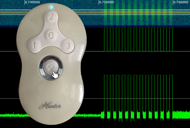
Preliminaries out of the way, its time to get hacking. Step one is recon. The remote is for a Hunter branded fan, has FCC ID IN2TX41, and a prominent “434MHz” frequency label on the back. The remote supports 4 fan speeds (Off, 1, 2, 3) and a light toggle that also acts as a dimmer when held. With the frequency explicitly listed, all that’s left is to plug in your SDR of choice (I’m using a bladeRF x40) and pop open GQRX. With the demodulation set to AM and the filter centered over 433.928MHz, I can hear packet bursts from the remote as I activate it (volume warning):
Some interesting things to note: the light on and fan off buttons send 4 bursts of data, where as the other buttons only send two. This will come into play later during the decoding and encoding phase. At first glance the signal it looks like the remote is likely doing a very simple Amplitude Shift Keying (ASK) modulation scheme. While GQRX is great for visual inspection, it isn’t the right tool for decoding data packets in more detail.
To go deeper its time to take a recording and switch tools, but there are some tricks to getting a successful recording:
- Make sure you don’t record the signal with the hardware receive frequency exactly set to it. You should offset your HW frequency to the left of your target signal to avoid the power spike centered at 0Hz. For example, if you want to record a signal at 433.928Mhz, set the frequency to 433.8Mhz. This depends on the signal bandwidth, but for the remote, the bandwidth is quite low so 100KHz is plenty of room.
- Record at a lower sample rate to save space. Your choice of sample rate ultimately depends on the data rate of your signal (higher data rate, more samples/s needed) and the minimum sample rate of your hardware.
I held the remote to the RX antenna for good signal, started the recording, and pressed the light on/off button.
This created the file gqrx_20210908_025853_433800000_2000000_fc.raw, which indicates I recorded at 433.8Mhz with a 2Msps rate.
Also keep in mind that you can only record signals with GQRX. The “play” functionality only displays the captured I/Q data and does not transmit.
Signal Replay using GNU Radio Companion
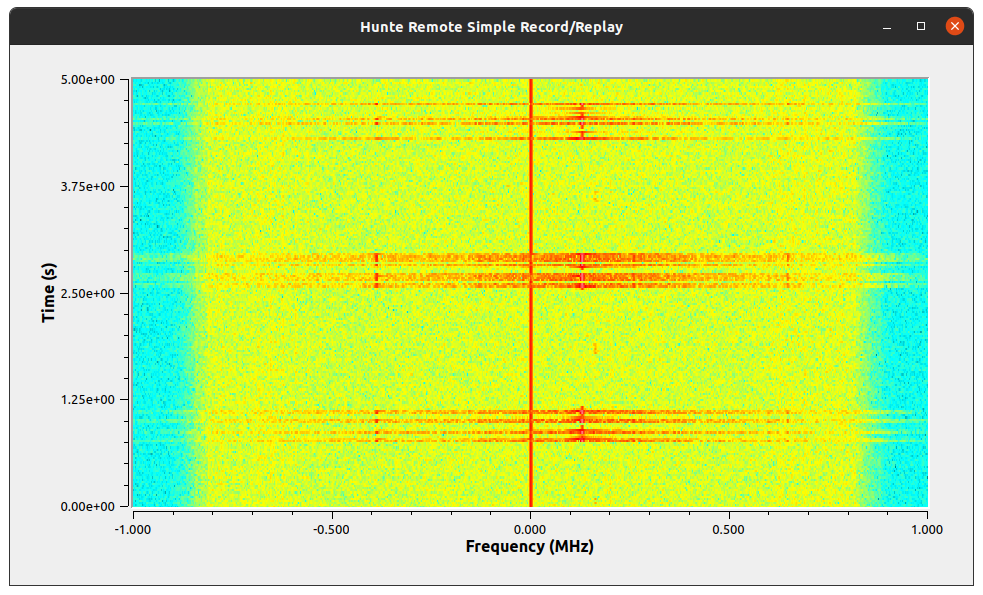
To replay signals, I’ll use GNU Radio Companion (GRC). Think of GRC as the visual frontend to GNU Radio’s DSP magic. Your primary workspace is the flowgraph – this lets you wire the inputs and outputs of blocks. These I/O ports have certain data types, as indicated by the color (see the Guided Tutorial for a reference). As GRC is just a frontend, what really happens is that a Python (or C++) script is automatically generated from your flowgraph on compilation. This script is then executed, possibly creating a QT GUI, and the output is piped to the output window (and your terminal). That’s really the uber basic idea, but beyond the nice and tidy blocks hides immense complexity that cannot be conquered by plugging things in randomly. Starting small, I designed a flowgraph to source the recorded input and sink it into an osmocom Sink (a SDR hardware abstraction block).

This flow graph takes advantage of the BladeRF’s simultaneous TX and RX functionality by showing the spectrogram and transmitting my recorded signal. Note that the frequency and sample rate match that of the recording. The greyed out blocks are disabled and can be activated to record and replay new signals from GNU Radio itself, doing away with the need to use GQRX. The “Multiply Const” block is used to increase the amplitude of some recordings that are too low to be picked up by the fan. Here’s the flowgraph in action:
With the right power and frequency the fan turns on and off repeatedly! The replay works without any modification of the signal, meaning there is no rolling-code like in other similar transmitters.
Decoding and Synthesizing
With all of the basic signal identification, capture, and replay proven, I could have stopped here. But I wanted to further understand the signal itself and be able to create it from scratch at the bit level. This would make enrolling new remotes easy all while avoiding large, “hardcoded” recordings. Until now, I’ve been treating this signal as a black box, but now its time to investigate the waveform itself.
Visual Decoding with Inspectrum
Inspectrum is a simple program for loading saved I/Q data and displaying the frequency waterfall along with the time-series waveform. It’s bare bones in terms of features, but it offers a few simple decoding plots and “cursors” to help measure distances between pulses. Loading the file recorded from GQRX (and double checking that the sample rate is 2000000 in my case) and scrolling along the X-axis (time), I eventually reach some promising pulses.
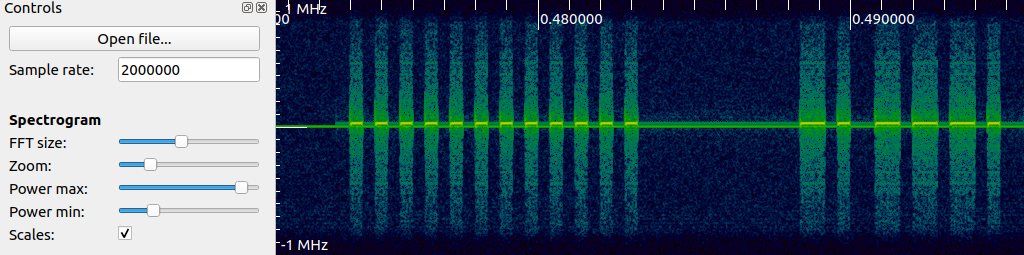
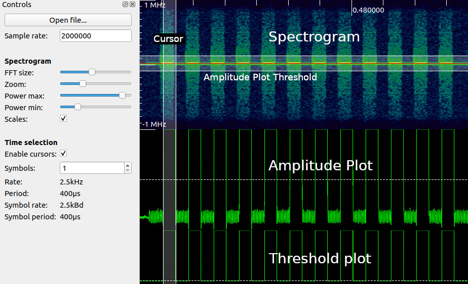
Unlike with GQRX, at this zoom level I can make out individual pulses of data! Based off of what I see now, this is a simple on-off keying (OOK) data transmission scheme, which is also quite popular in garage door openers. To clean up this data, I added two derived plots: first right click on the spectrogram and add “amplitude plot”. Adjust the filter width and center line transparent rectangle to get somewhat clean pulses on the amplitude plot. Next add a threshold plot to the amplitude plot to further clean up the pulse train. Finally, enable the cursors, set the symbols to 1, and zoom in to measure a single pulse width. This will allow us to recover the symbol rate a.k.a the baudrate. In the Hunter remote’s case, the symbol rate is \(2500~\text{symbols/s}\) or 1 symbol every \(1000000~/~2500 = 400\mu s\). This number will be very important coming up when synthesizing and decoding the message properly. My Inspectrum view now looks like this (data annotations added by me).
By extending the number of symbols, I can delimit the data packet into distinct symbols, zero or one. I extended the cursor to encompass 234 symbols. Finally, I right clicked on the threshold plot with the cursors active and hit “Extract Symbols”. This gave the following bit sequence:
101010101010101010101010000000000000110110110100100100100100110110110110110100100100100110110100110110110100100100100110110110110110110110110100100110110100110100100100110100100100100100100100100110110110100110110110110110110110110100
Inspecting the sequence, there are some interesting characteristics:
- The first bits are a sequence of 1010’s followed by zeros. This is likely a signal preamble to help the receiver synchronize to the signal
- The following bits are sequences of 110 and 100, likely representing binary 1’s and 0’s respectively
Assuming that each actual data bit takes 3 symbols for each bit, our effective bit rate is \(2500~/~3 = 833.3~\text{bits/s}\) which is quite slow. Ignoring the preamble and replacing these sequences in the data with their corresponding bits yields:
preamble | 101010101010101010101010 (24 symbols)

quiet period | 000000000000 (12 symbols)

data | 111000001111100001101110000111111110011010001000000001110111111110
       (198 symbols, 66 bits)
I don’t know the data format yet, but with this first payload of bits (non decoded), I can copy this into a new flowgraph to transmit from scratch.
Synthesizing OOK with GRC
Armed with the knowledge of how to decode the signal from the remote visually and extract the raw bitstream of it over the air, I created a flowgraph to transmit this signal over-the-air from scratch – no recording required.
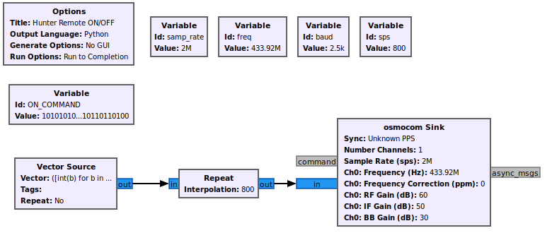
To achieve this, GNU Radio has a “Vector Source” block that can store a Python iterable (list, tuple, etc.). I created a variable ON_COMMAND with the raw bitstring I extracted from Inspectrum as a string and then created the source with the value of a Python expression:
([int(b) for b in ON_COMMAND] + [0]*64)*2 + [0]*4096This expression does a few things: converts the ON_COMMAND string to a vector of binary values, adds a “silence gap” of 64 symbols after (to allow for command processing), repeats the command twice, and finally adds a 4096 gap of silence at the end to change the blinking delay. This source is fed into a “Repeat block”, which is crucial for getting the signal timing right. The number of repeats is calculated as the number of samples per symbol. This is calculated as
\[\text{SampleRate}~/~\text{BaudRate} = 2000000~/~2500 = 800~\text{sps}\]
The way to conceptualize this block is that it stretches the individual sample points to form a square wave matching the baud rate of our remote.
Pressing play on this flowgraph will drain the source once (non repeating) turning the light on. Success! I can now transmit arbitrary bits to the fan. There’s no video for this part as the flowgraph is a command line program, but take my word for it.
Demodulating OOK with GRC
With synthesis achieved, I decided to automate the process of demodulating and decoding the remote’s signals. This would allow me to easily capture all of the signals from both remotes I have and potentially listen for other remote commands as well. Unlike replaying a signal or even synthesizing a signal, demodulation is a significantly harder task. To properly demodulate even a simple OOK signal a receiver needs to be able to synchronize with the transmitting source. By synchronize I mean the receiver needs to know when during its time reference to take a sample of data over-the-air. Here is the flowgraph which I will be explaining in the following paragraphs:
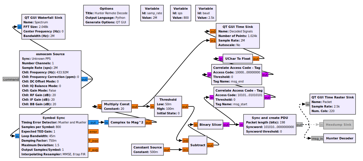
To achieve symbol decoding in real-time, I used the “Symbol Sync” block. I’ve looked into this magic block, but I can’t pretend to understand it or its parameters very well. At a high level what it does is performs a type of timing recovery to align with an asynchronous signal. In our case, the OOK symbol has a known baudrate and a known samples per symbol. This information is fed into this block which ends up downsampling the incoming over-the-air data into individual symbols (single samples). The output of this block is a complex number (I and Q) which has a lower sample rate (2500 samples/s). From here this IQ data is converted into a float and squared to increase its magnitude. The following blocks apply thresholding, similar to how I did it in Inspectrum, which is fed into the binary slicer to create a stream of unsigned chars (0 or 1). This byte stream then goes into two different directions: into a “Correlate Access Code - Tag” block and a “Sync and Create PDU” block. The correlate access code path merely searches for a defined sequence of bytes in the stream and annotates (tags) the sample stream for display in the Time Sink, if found. It is completely optional and for display only.
The other path is more complicated and is where I had to resort to using an out-of-tree GNU Radio module from the gr-satellites project. This project can be installed via PyBOMBS: pybombs install gr-satellites. Note that you may need to edit the recipe’s Git branch in $HOME/.pybombs/recipes/gr-recipes/gr-satellites.lwr to maint-3.8 (or the version of GNU Radio your PyBOMBS installed) for the install to compile properly.
The “Sync and Create PDU” block performs a similar task to the correlate access code block: it takes a bitstring that is to be matched against the input stream. If this bitstream is found (with some configurable error margin), a PDU (just a byte vector) is created and emitted. This block is crucial for only receiving valid messages. The newly created PDU goes into a “Time Raster Sink”, which gives a nice “barcode” like display of a message’s bits, and also into the last block – one I made myself – “Hunter Decoder”. This decoder implements a simple embedded python script (meaning inline with the flowgraph’s .grc file) that takes in a PDU, removes the preamble, decodes the message (110 -> 1, 100 -> 0), and finally prints the bit string. The full code is here:
from gnuradio import gr
import pmt

class blk(gr.sync_block):
    def __init__(self):
        gr.sync_block.__init__(
            self,
            name='Hunter Decoder',
            in_sig=None,
            out_sig=None
        )
        self.message_port_register_in(pmt.intern('msg_in'))
        self.set_msg_handler(pmt.intern('msg_in'), self.handle_msg)

    def handle_msg(self, msg):
        arr = list(pmt.to_python(msg)[1])
        msg_str = "".join([str(x) for x in arr])
        decoded = msg_str.replace("110", "A") \
                         .replace("100", "B") \
                         .replace("A", "1") \
                         .replace("B", "0")

        #print("msg = %s" % (msg_str))
        print("dec = %s" % (decoded))
With this flowgraph I can easily capture and decode signals from all buttons of the remote and copy and paste them for further reverse engineering and future synthesis. Here’s the flowgraph in action:
The flowgraph’s GUI shows the spectrum in the top-left, the “barcode” raster display in the top right, and the raw symbol sync signal, along with the thresholded signal, in the bottom time display. The console prints received frames with an intact preamble. If you look closely, you’ll notice that the data reception is sometimes unreliable. This is due to my ignorance in making a robust decoder, which would require improving the signal conditioning before the sync block (e.g. by adding match filters and auto gain control) and also by tuning the sync block’s parameters (e.g. TED gain, loop bandwidth, damping factor) to my application. I made attempts to improve this, but didn’t succeed. But as long as the remote is within a meter of the SDR’s RX antenna, the signal is usually decoded properly.
Reverse Engineering the Signal Format
With the ability to quickly receive and decode Hunter remote signals, I was able to gather a library of button presses from two remotes (after decoding). By lining these signals up vertically, I was able to spot some clear patterns and start dividing the messages up into fields. The full decoding notes are available on GitHub, but I’ll give a brief overview of what I learned in this table:
+-------------+----------------------------------------+-----+---------------------+
|  CMD NAME   |               REMOTE ID                | SEP*|       COMMAND       |
+-------------+----------------------------------------+-----+---------------------+
ON_PRESS        111000001111100001101110000111111110011 01000 1000000001110111111110
ON_RELEASE      111000001111100001101110000111111110011 01000 0001001101111110110010
FAN_0_PRESS     111000001111100001101110000111111110011 01000 0000000011111111111100
FAN_0_RELEASE   111000001111100001101110000111111110011 01000 0001000101111110111010
FAN_1           111000001111100001101110000111111110011 01000 0000000101111111111010
FAN_2           111000001111100001101110000111111110011 01000 0001000001111110111110
FAN_3           111000001111100001101110000111111110011 01000 0010000001111101111110
PAIR%           111000001111100001101110000111111110011 01000 0010000011111101111100

* - Assumes that 01000 is a common delimiter (SEP)
% - To pair, hold FAN_0 and FAN_3 for 4 seconds. CMD repeats continuously.
    Pairing only available right after fan cold power on

PREAMBLE = 101010101010101010101010000000000000
COMMAND_GAP = 00000000000000000000000000000000000000000000000000000000000000
ON_COMMAND = (PREAMBLE + ON_PRESS + COMMAND_GAP)*2 + (PREAMBLE + ON_RELEASE + COMMAND_GAP)*2
                         ^^^^^^^^                                ^^^^^^^^^^
                            \________________________________________/
                                 |
  [ Command is encoded ]---------'
  [ Assumes remote ID is set ]---'
As I mentioned earlier, the ON and FAN_0 buttons in that they have a PRESSed and RELEASEd command. This is because the ON button can be used for dimming. For the FAN_0 button, I’m not clear why is has two states.
While I was able to do this reverse engineering manually, another great tool worth exploring in the future is Universal Radio Hacker (URH). It is specifically meant for capturing, reverse engineering, and replaying signals. I briefly played with it for this project, but since the signal I was capturing was so simple, I didn’t need many of its features and stuck with GRC instead. Plus I wanted to create my own flowgraphs for experience.
Building a Virtual Remote
Until now I’ve used GRC to inspect, decode, and synthesize signals. GRC is fairly straight forward once you get over the flowgraph learning curve but where a complex flowgraph excels in intimidation factor, it lacks a bit in polish. So to tidy up the User Experience, I exported my replay flowgraph as a GNU Radio Python script and slapped a custom standalone QT GUI in front. Also instead of a programmer-esque GUI with ugly buttons, I used a cutout of the remote itself and mapped buttons to the semi-tranparent image.
When a button is hit, the transmit LED lights, just like on the remote, and a GNU Radio flowgraph is executed with the specified fan ID and command. It’s really neat to control a physical object with a mouse click. Here’s the video of it in action – no more physical remote needed (just a $400 SDR hah):
Does anyone else get reminded of old keygens when they see floating apps like this (like back in the day of C++ Winforms with Magenta transparency keying)? No? Just me?
This project was a great excuse to build confidence with GNU Radio and more in-depth SDR experience. I went from signal recon, decoding, command synthesis, to finally ending with a desktop remote. I’ve released more decoding notes, the GRC flowgraphs, and virtual remote GUI on GitHub for your reference: https://github.com/grant-h/hunter_remote. Thanks for reading!
Resources
- Software Defined Radio and Decoding On-off Keying by Compass Security
This was a great help in getting the initial record, inspectrum, replay flow working - Reverse engineering a ceiling fan by Clayton
A very similar blog also on reverse engineering a ceiling fan with on-off keying. - Studying radio communications with GNURadio and SDR by Foo-Manroot
Another excellent article on brute forcing an OOK scheme to turn on a switch. - Software Defined Radio with HackRF by Great Scott Gadgets
One of the few tutorial series for SDR and DSP. - GQRX - Practical Tips and Tricks by Alexandru Csete
A great official reference for effectively using GQRX.