CRC-32 VLSI Design Die Shots
This is a follow up to my previous post on creating a CRC-32 chip from scratch using Cadence. Check it out as it goes over the design details.
tl;dr: see die shot images
After submitting my CRC-32 design to MOSIS for fabrication, I had to wait quite a while for the results (over 6 months), but considering it was
- Free
- An actual chip that I can physically hold in my hands
- Something I designed myself from scratch
I was willing to wait. The wait was finally over in late December of 2015.
A lot has changed since then. I graduated from UCF with my bachelors degree in Computer Engineering and I moved to Gainesville to attend the University of Florida as a 1st year PhD student. As a long-ago class project most would have left it at receiving the physical chips. But that’s not the whole project.
When I first received the chips, I wanted to see what the die looked like, but I just didn’t have the imaging equipment required to see a 1.2mm x 1.2mm object with \(0.3~\lambda\) features (\(300nm\) is quite ancient, but it was free).
As luck would have it, I attended the FICS Conference in January 2016 and one of the sponsors was Carl Zeiss. Two friendly sales reps were there showing off one of their fancy optical microscopes. I asked if I could test it out with a “sample” and they happily let me drive the microscope.
Without further ado, here are the images (click for HQ)
-
- Die top view with interesting lighting mode
-
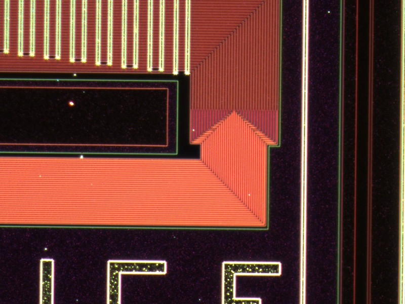
- Close up of 32-bit bus

-
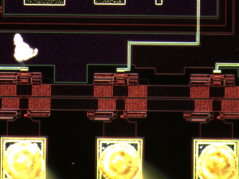
- Close up of a I/O pin and dust particle

-
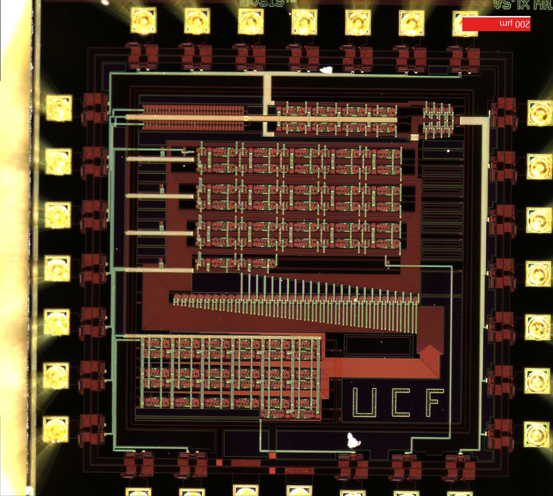
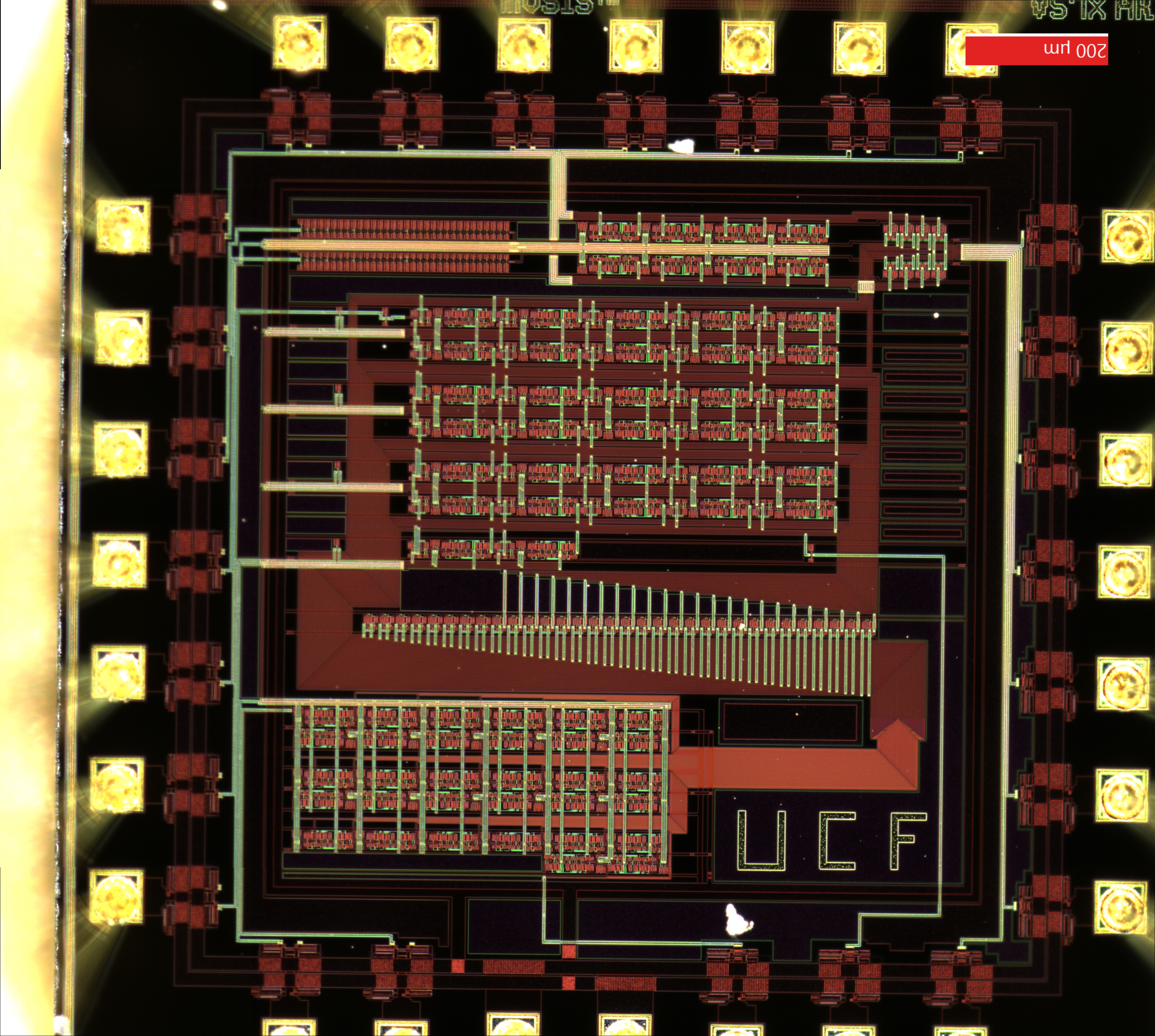
- High quality chip die shot
-
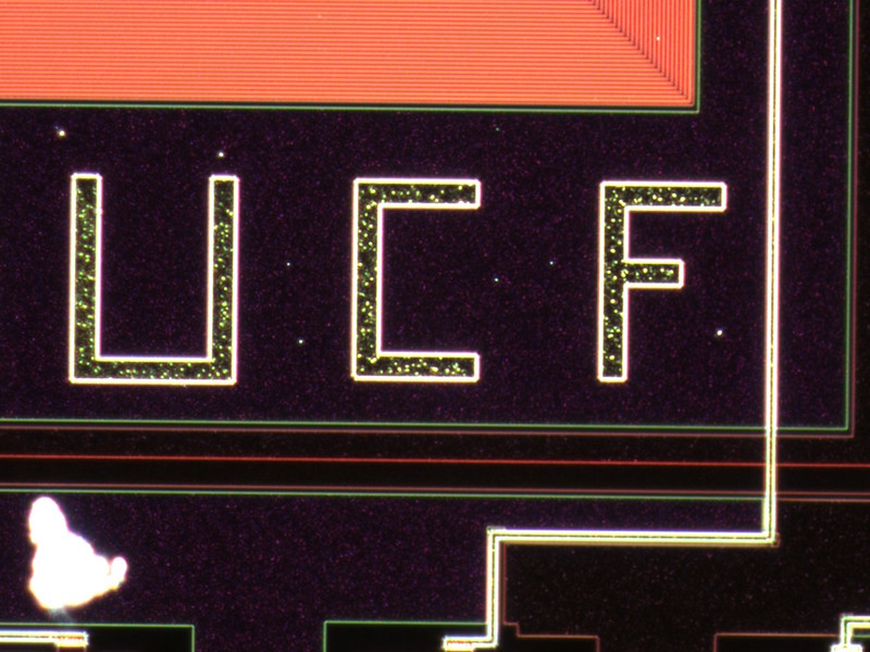
- Close up of UCF logo
